Acquiring and Displaying Waveforms
3–10
TDS 684A, TDS 744A, & TDS 784A User Manual
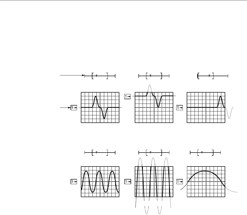
The Channel Reference icon, at the left side of the display, points to ground on
the waveform record when offset is set to 0 V. The oscilloscope contracts or
expands the selected waveform around this point when you change the vertical
scale.
The Record View, at the top of the display, indicates where the trigger occurs and
what part of the waveform record is displayed.
Original Position Positioned Vertically Positioned Horizontally
Original Scale Scaled Horizontally
Record View
Channel Reference Icon
Scaled Vertically
Figure 3–5: Scaling and Positioning
Check the Vertical Readout at the bottom-left part of the display to read the
volts/division setting for each displayed channel (the selected channel is in
inverse video). (See Figure 3–6.)
The TDS Oscilloscope permits you to change vertical scale and position quickly
from the front panel using dedicated control knobs. To change the vertical scale
and position:
1. Turn the vertical SCALE knob. Note only the scale of the selected wave-
form changes.
To Check the
Vertical Scale
To Change Vertical Scale
and Position


