Hardware and Software Installation
Rev 1.4 Draft Mar.08 29
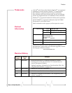
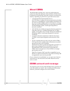
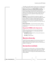
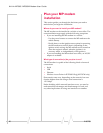
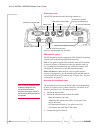
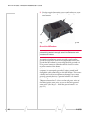
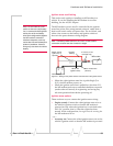
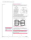
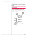
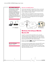
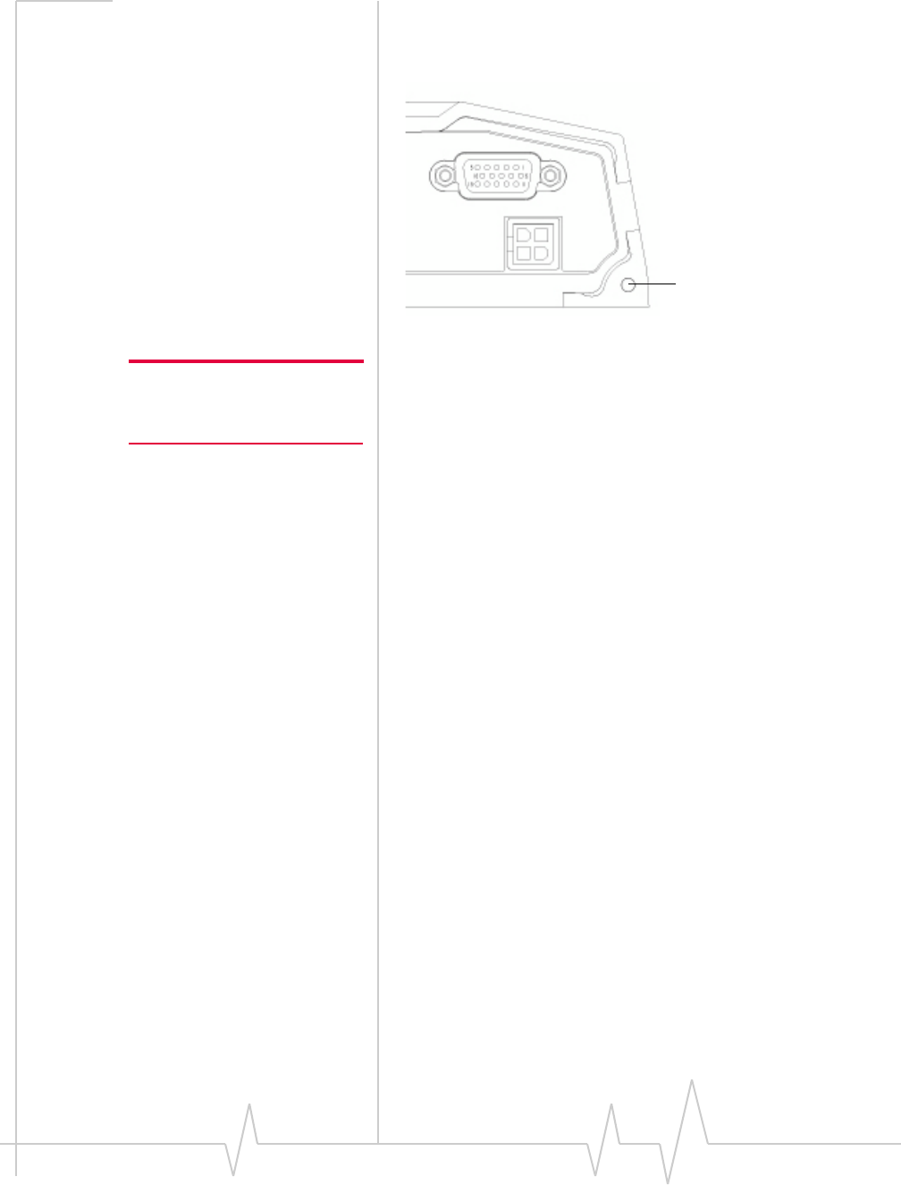
Youcanalsouseagroundscrewontheconnectorpanelofthe
MPmodem.Usea16‐gaugewireifyouchoosetouseaground
screw.Agroundscrewisnotrequiredaslongasthepower
harnessisproperlygrounded.
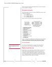
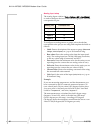
Figure 3-4: The ground screw connector on the connector panel.
Note: Tighten cables connected
to the MP modem by hand. Do
not use tools.
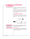
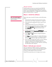
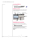
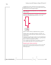
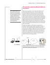
Step 2 — Mount the antennas and install
the cables
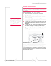
TheMP595WmodemhastwoMainRFantennaconnectors
andoneGPSantennaconnector.TheMP 595Whasan
additionalRFantennaconnectorforanAPantenna.TheMP
modemrequiresanRFantennatoconnecttothewireless
network.ThesecondRFconnectorisoptionalandallowsfor
receivediversity.
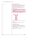
Thebuilt‐inGPSmodulerequiresadedicatedGPSantennaor
acombinationantennawithcablestoboththeMainRFand
GPSantennaconnectorsontheMPmodem.
IfyoualreadyhaveanMPmodemcombinationGPSantenna,
youcanre‐useitwithyournewMPmodem.Thisantennahas
twoleads
—oneforMainRF(TNCconnector)andoneforGPS
(SMAconnector).
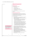
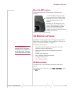
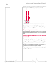
Main RF antenna
UseanapprovedMainRFantennatoconnecttothewireless
network.Theantennamusthave50
ohmsimpedanceanda
cablewithaTNCconnector(orSMAconnectoriftheantenna
isbeingusedforreceivediversity),aswellasthefollowing
characteristics:
• Thetotalmaximumgain,includingcableloss,mustnot
exceed4.15
dBi(iftheantennaoperatesonthePCSband)
or5.1
dBi(iftheantennaoperatesonlyontheCellular
band).
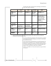
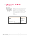
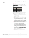
• Theantennamusttransmitandreceiveonthenecessary
frequencybandsinyourcoveragearea.TheMPmodem
supportstheseRFbands:
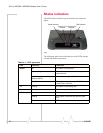
If you are using a ground screw,
Power
I/O
insert it here.