28
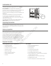
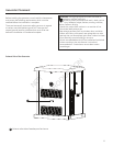
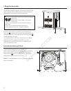
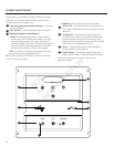
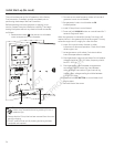
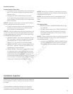
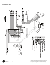
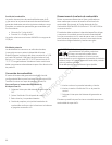
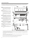
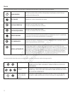
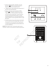
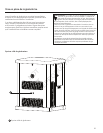
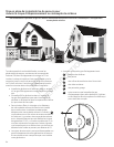
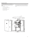
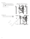
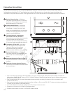
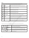
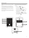
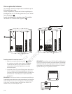
System Control Board
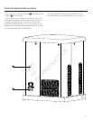
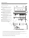
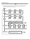
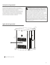
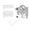
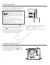
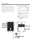
The generator control board, located inside the generator,
under the roof, is shown below. Brief descriptions of the
controls used during installation are:
A
- Menu/Programming Navigation Buttons —SeeMenu
section for details
B
- Mini USB Port—AuthorizedDealerServiceUseOnly
C
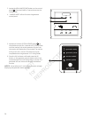
- Generator Operation Control Buttons —
•“AUTO”Normal operating position. Press and hold
button to put unit into Automatic mode. If an utility
power outage is sensed, the system will start the
generator. When utility power is restored, auto lets the
enginestabilizeinternaltemperatures,shutsothe
generator, and waits for the next utility outage.
•“OFF”Turnsorunninggenerator,preventsunitfrom
starting, and resets any detected faults.
OFF must be pressed and held for more than 5 seconds in
order to reset service codes.
•“MANUAL”Used to manually start the generator.
- “AUTO” LED—LEDwilllightwhenunitisplacedinto
Auto mode. LED will blink if exercise cycle is not set or
set to OFF.
D
– 15 Amp Fuse—ProtectsthehomegeneratorDC
control circuits. If the fuse has ‘blown’ (melted open)
or was removed, the engine cannot crank or start.
Replace the fuse using only an identical ATO 15A fuse.
One spare fuse is supplied with the unit.
E
- Cover—Thisprotectivecovermustbeopenedto
access the fuse and the USB port.
F
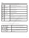
- Digital Display—Displaysgeneratormode,menu
options, service codes, and service engine indicators
More information may be found in Controls in the
operator’s manual.
ok
menu
esc
auto
off manual
A
B
C
D
F
E
*
*