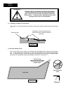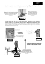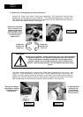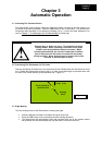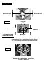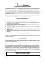
Insert the two perimeter wire ends into the male connector as shown in Figure 1.17. Using a small flat
blade screwdriver, fasten the two screws tightly to hold the wire. Figure 1.17.
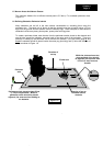
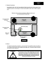
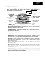
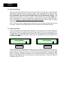
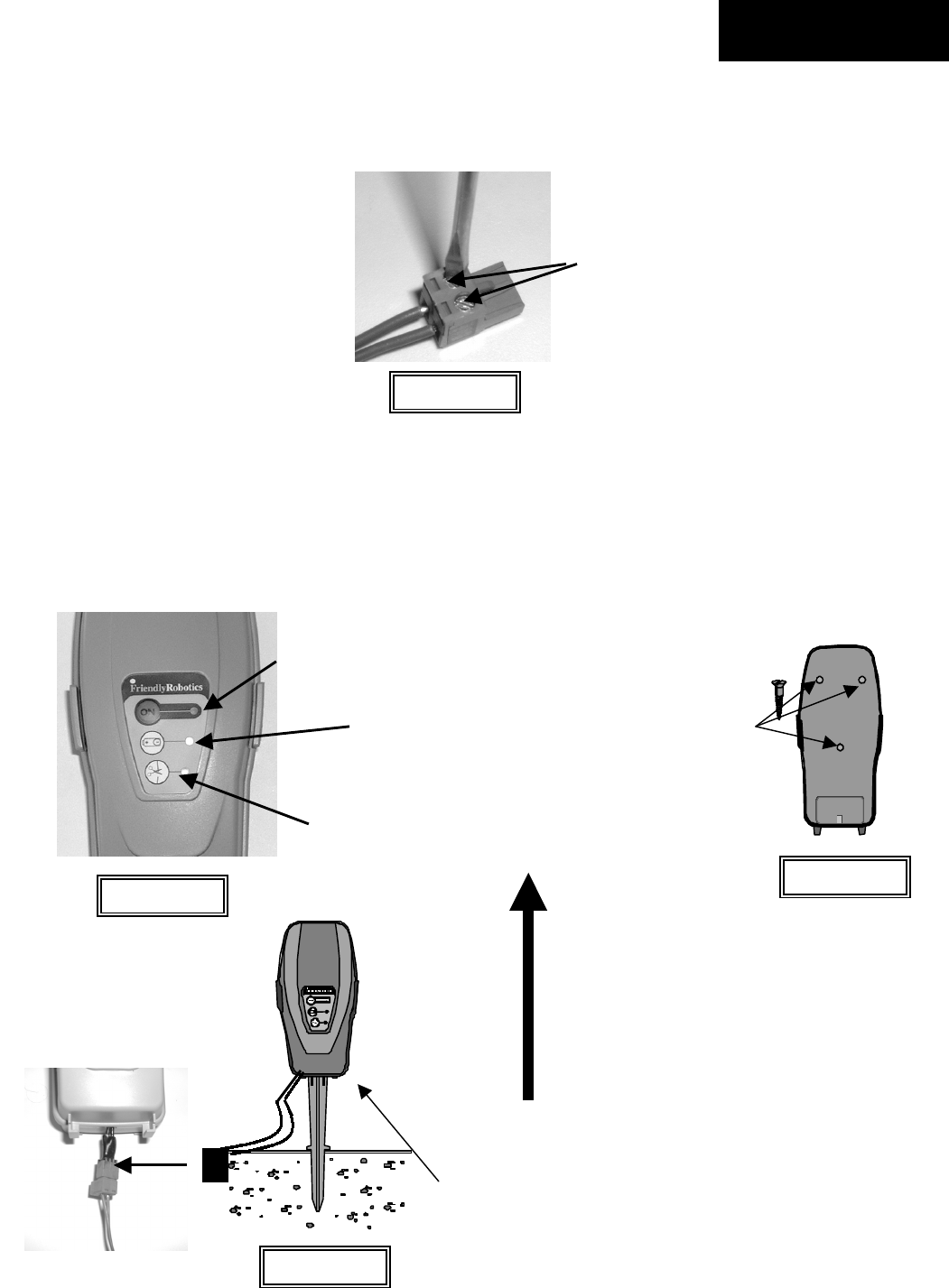
A small flashing green light next to the ‘On’ button indicates the system is on and functioning
correctly. Figure 1.18. The Perimeter Switch also has an indicator for low batteries and for a
disconnected/broken perimeter wire. Figure 1.18. The Perimeter Switch has an automatic shutoff
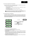
feature, eliminating the need for you to turn it off after each use. It will shut itself off after 5 continuous
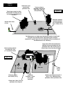
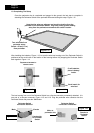
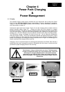
hours of operation. Place the Perimeter Switch on the stake as shown in Figure 1.19 or mount on a
fixed surface as shown in Figure 1.20.
Figure 1.17
Strip back ¼ inch (6 mm) of insulation
from each wire end and insert each
perimeter wire end into hole of
connector.
Using a small flat blade
screwdriver, tighten these
two screws to secure the
perimeter wires into the
connector
On button and
indicator light
Low battery
indicator light
Disconnected/broken
wire indicator light
Figure 1.18
Mounting the Perimeter
Switch using three
mounting bosses on
back cover
Perimeter Switch with
mounting stake attached.
Disconnect Perimeter Switch
connector and move switch to
new plot.
Figure 1.20
Figure 1.19
The Perimeter Switch MUST be mounted
vertically in order to maintain its’ water
resistance
Chapter 1
Page 15