Maintenance
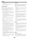
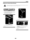
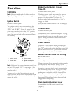
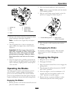
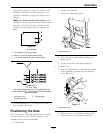
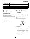
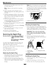
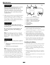
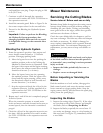
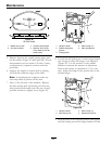
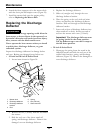
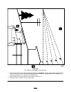
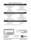
Figure 43
1. Opposing blade edge, in position for measuring
2. Level surface
3. Second measured distance between blade and surface
(B)
WARNING
A worn or damaged blade can break, and a
piece of the blade could be thrown into the
operator's or bystander's area, resulting in
serious personal injury or death.
• Inspect the blade periodically for wear or
damage.
• Replace a worn or damaged blade.
A. If the difference between A and B is greater
than 1/8 inch (3mm) replace the blade with a
new blade. Refer to Removing the Blades and
Installing the Blades.
Note: If a bent blade is replaced with a new
one and the dimension obtained continues
to exceed 1/8 inch (3mm), the blade spindle
could be bent. Contact an Authorized Exmark
Dealer for service.
B. If the variance is within constraints, move to
the next blade.
Repeat this procedure on each blade.
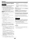
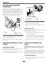
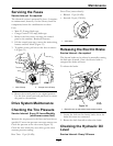
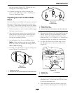
Checking for Loose Blades or
Damaged Spring Disc Washers
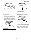
1. Place a wrench on the blade bolt and torque to
35-65 ft-lb (47-88 N-m).
2. With the wrench still on the blade bolt, hold
the blade spindle stationary and using a rag or
thickly padded glove, try to rotate the blade. If the
blade rotates relative to the spindle guard without
further tightening the blade bolt, the spring
disc washer has been attened or damaged and
the bolt and washer assembly must be replaced
(Figure 44). Refer to Removing the Blades and
Installing the Blades.
3. Once the blade has been removed, inspect the
spring disc washer. If the washer appears to be
damaged (the washer surface has been marred)
or attened, the bolt and washer assembly must
be replaced.
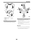
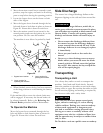
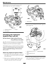
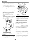
Removing the Blades
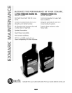
The blades must be replaced if a solid object is hit, if
the blade is out of balance, or the blade is bent. To
ensure optimum performance and continued safety
conformance of the machine, use genuine Exmark
replacement blades. Replacement blades made by
other manufacturers may result in an unsafe machine.
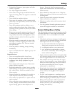
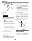
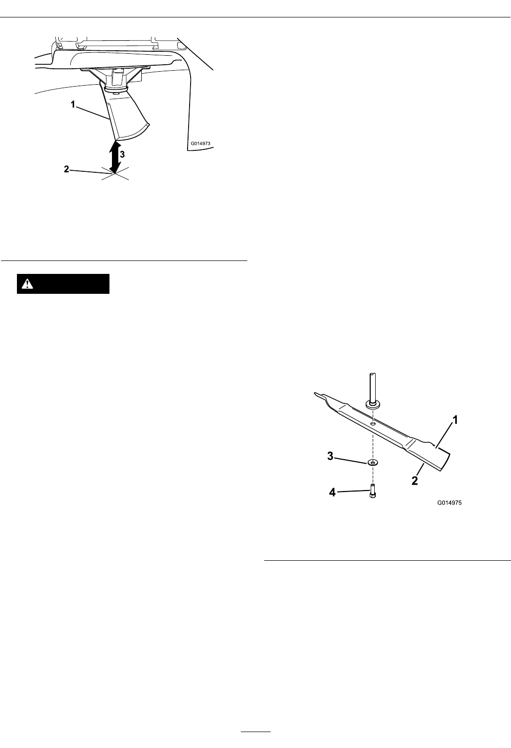
Hold the blade end using a rag or thickly-padded
glove. Remove the blade bolt, curved washer, and
blade from the spindle shaft (
Figure 44).
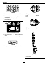
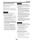
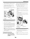
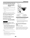
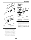
Figure 44
1. Sail area of blade 3. Curved washer
2. Blade 4. Blade bolt
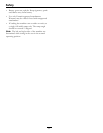
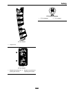
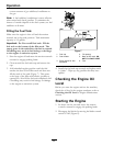
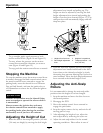
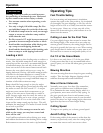
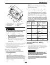
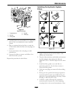
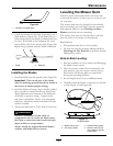
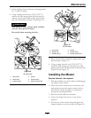
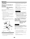
Sharpening the Blades
1. Use a le to sharpen the cutting edge at both ends
of the blade (Figure 45). Maintain the original
angle. The blade retains its balance if the same
amount of material is removed from both cutting
edges.
44