IMPORTANT
Power Supply Board must be re
1.
Turn off power to the sign by turning off the corresponding Constant Current Regulator (CCR)
power. (WARNING: W
ait five minutes after sign power is turned off
will allow any residual high voltage
WARNING
Failure to turn off power to the sign and wait five minutes could result
in severe injury or death.
2.
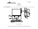
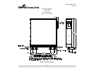
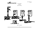
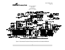
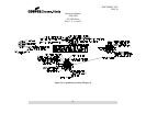
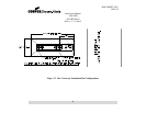
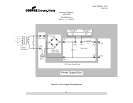
With your multimeter set to DC Volts, verify that the Power Supply Output Volta
VDC at TP6 (Positive lead) and TP3 (Negative Lead) as indicated in Figure 22. If the Power Supply
Output Voltage is greater than 30
drops below 30-
VDC before you proceed wit
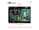
3. Remove
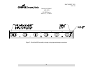
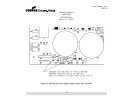
input power cabling at CN1, CN2, CN3, CN11, CN17,
4. Remove
LED Power Supply Cable at CN9
5.
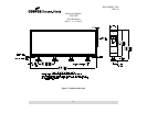
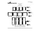
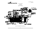
Remove the three nuts that secure the main heat sink to the Power Supply Box.
6. Remove the six
screws that fasten the Power Supply Board onto the Power Supply Box.
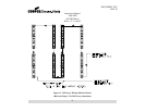
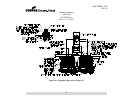
7.
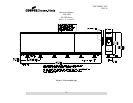
Remove the Power Supply Board
studs extending from the side of the Power Supply Box.
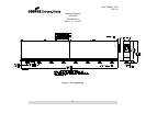
8. Slide the
Supply Box.
9.
Fasten board to the Power Supply Box with six mounting screws.
10.
Attach the three nuts that secure the heat sink to the studs extending from the side of the Power
Supply Box.
11.
Connect the LED Power Supply cable at CN9.
12.
Connect the input power cabling at CN1, CN2, CN3, CN11, CN17, & CN18.
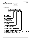
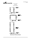
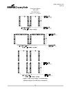
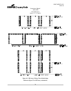
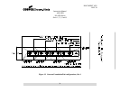
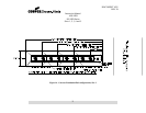
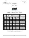
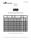
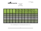
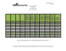
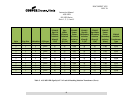
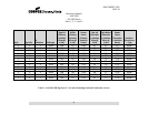
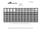
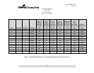
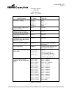
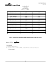
13. Set the jumpers JP1 & JP2
for the sign style, size, and number of modules as shown in Table 1 or 2.
(For locaction, see Figure 18)
Instruction Manual
AGS-LED
858 LED Series
Sizes 1, 2, 3, 4 and 5
18
WARNING:
Power Supply Board must be re
-calibrated after
(see Section 10.11).
Turn off power to the sign by turning off the corresponding Constant Current Regulator (CCR)
ait five minutes after sign power is turned off
will allow any residual high voltage
stored in Power Supply
WARNING:
Failure to turn off power to the sign and wait five minutes could result
in severe injury or death.
With your multimeter set to DC Volts, verify that the Power Supply Output Volta
VDC at TP6 (Positive lead) and TP3 (Negative Lead) as indicated in Figure 22. If the Power Supply
Output Voltage is greater than 30
-
VDC, then you must wait until the Power Supply Output Voltage
VDC before you proceed wit
h the next step.
input power cabling at CN1, CN2, CN3, CN11, CN17,
& CN18
LED Power Supply Cable at CN9
(See Figure 15).
Remove the three nuts that secure the main heat sink to the Power Supply Box.
screws that fasten the Power Supply Board onto the Power Supply Box.
Remove the Power Supply Board
Assembly by sliding the attached main heat sink
studs extending from the side of the Power Supply Box.
rd onto the mounting studs extending from the side of the Power
Fasten board to the Power Supply Box with six mounting screws.
Attach the three nuts that secure the heat sink to the studs extending from the side of the Power
Connect the LED Power Supply cable at CN9.
Connect the input power cabling at CN1, CN2, CN3, CN11, CN17, & CN18.
for the sign style, size, and number of modules as shown in Table 1 or 2.
DOCUMENT 1025
REV. B
.
Turn off power to the sign by turning off the corresponding Constant Current Regulator (CCR)
. This
bleed off.)
Failure to turn off power to the sign and wait five minutes could result
-
VDC at TP6 (Positive lead) and TP3 (Negative Lead) as indicated in Figure 22. If the Power Supply
VDC, then you must wait until the Power Supply Output Voltage
.
screws that fasten the Power Supply Board onto the Power Supply Box.
rd onto the mounting studs extending from the side of the Power
Attach the three nuts that secure the heat sink to the studs extending from the side of the Power
for the sign style, size, and number of modules as shown in Table 1 or 2.