9 Installation
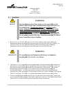
NOTICE
Sign foundations/pad and their design are the responsibi
installer and/or airport and recommendations/suggestions herein are
covers,
series isolation transformers
isolation transformer secondary cable extend
ground wire and connectors, floor flange anchor bolts and hardware
are not included as part of the sign.
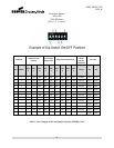
a. Refer to FAA AC 150-5345-
18F section 14 for Taxiway Guidance Sign location and for the
perpendicular distance from the defined pavement edg
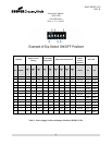
section 25 of FAA AC 150-
perpendicular distance from the defined pavement edge to the near side of the sign
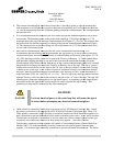
IMPORTANT
FAA specifications and Engineering Briefs may be obtained by
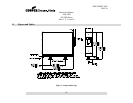
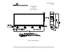
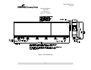
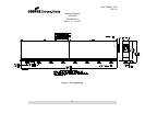
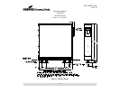
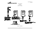
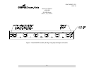
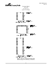
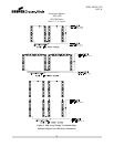
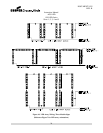
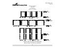
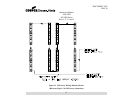
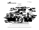
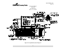
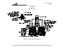
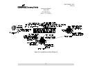
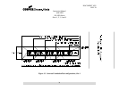
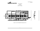
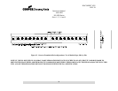
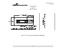
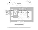
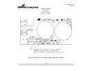
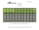
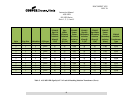
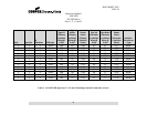
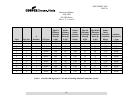
b. See Figures 12-17
for suggested concrete foundation/pad. Concrete foundations/pads should be of
adequate mass, reinforcement, and psi strength rating for the
body and floor flange anchors must endure at its maximum plus a safe
foundation/pad should be installed in soil conditions that will help facilitate drainage and
foun
dation/pad support. The floor
sustained force on the sign body
25684-1 Floor Flange. See
c.
Concrete foundations/pads should extend at least 12 inches below the local frost line. Contact your
loc
al or regional building inspector if the depth is unknown for your area.
extend at least 1 foot beyond the sign body to minimize damage from mowers.
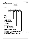
Instruction Manual
AGS-LED
858 LED Series
Sizes 1, 2, 3, 4 and 5
3
WARNING:
Sign foundations/pad and their design are the responsibi
installer and/or airport and recommendations/suggestions herein are
Transformer housing and baseplates
series isolation transformers
, primary
isolation transformer secondary cable extend
er,
(if required), heat shrink kits,
ground wire and connectors, floor flange anchor bolts and hardware
are not included as part of the sign.
Underlined i
-Hinds Airport Lighting.
18F section 14 for Taxiway Guidance Sign location and for the
perpendicular distance from the defined pavement edg
e to the near side of the sign.
-18F for Runway Distance
Remaining Sign location and
perpendicular distance from the defined pavement edge to the near side of the sign
.
WARNING:
FAA specifications and Engineering Briefs may be obtained by
site: www.faa.gov.
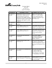
for suggested concrete foundation/pad. Concrete foundations/pads should be of
adequate mass, reinforcement, and psi strength rating for the
maximum sustained force on
body and floor flange anchors must endure at its maximum plus a safe
foundation/pad should be installed in soil conditions that will help facilitate drainage and
dation/pad support. The floor
flange anchor bolt material should also meet the maximum
sustained force on the sign body
plus a safety
margin and must be ½ inch in diameter for use with the
for estimated maximum
sustained force on the sign body.
Concrete foundations/pads should extend at least 12 inches below the local frost line. Contact your
al or regional building inspector if the depth is unknown for your area.
The foundation/pad should
extend at least 1 foot beyond the sign body to minimize damage from mowers.
DOCUMENT 1025
REV. B
Sign foundations/pad and their design are the responsibi
lity of the
installer and/or airport and recommendations/suggestions herein are
and/or
, series
ground wire and connectors, floor flange anchor bolts and hardware
18F section 14 for Taxiway Guidance Sign location and for the
Similarly, see
Remaining Sign location and
FAA specifications and Engineering Briefs may be obtained by
for suggested concrete foundation/pad. Concrete foundations/pads should be of
maximum sustained force on
the sign
foundation/pad should be installed in soil conditions that will help facilitate drainage and
flange anchor bolt material should also meet the maximum
margin and must be ½ inch in diameter for use with the
sustained force on the sign body.
Concrete foundations/pads should extend at least 12 inches below the local frost line. Contact your
The foundation/pad should