


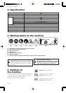
GB-8
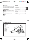
BKZ4500DL / BKZ5000DL
6. Set up
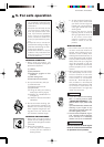
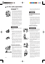
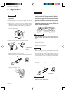
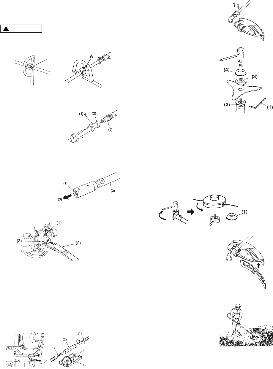
INSTALLING HANDLE
• Mount the handle to the shaft tube and clamp it at a
location that the edge of CE label is matched with the
handle.
WARNING
• Stop tightening the screws when the gap A be-
comes zero.
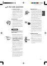
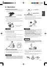
FLEXIBLE SHAFT
1. Remove the bolt located on the joint of the shaft tube.
2. Match the groove of the liner with the threaded hole
and fix with screw securely.
3.
While rotating the flexible shaft located on the opposite
end from the liner, insert the flexible shaft into the joint
until it is tightly connected. (Note that it is normal at this
time for the flexible shaft not to project from the liner.)
4. Put the engine side end of the flexible shaft into the
clutch housing, making the hole on the shaft upside.
Push it on until the stopper catches the hole.
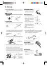
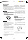
5. Pass the end of the wire on the side of the blade
through the sleeve of the connector case.
6. Insert the end of the wire on the side of the blade into
the end of the wire on the side of the engine, and put
the sleeve over the connected part (Fig. 6).
7.
Align the throttle wire and the sleeve with the hollow of
the connector case and insert them into the connector
case, and close the connector case. In order to close
the connector case, align half the surface of the con-
nector case with the other half surface and press the
upper half surface strongly with your fingers.
(1)Bolt
(2)Joint
(3)Groove
(1)Flexible shaft
(2)Liner
(3)Clutch housing
CE label
(1) Stopper
(2) Flexible liner
(3) Clutch housing
(1) The end of the
wire on the side
of the engine
(2) Sleeve
(3) The end of the
wire on the side
of the blade
(4) Connector case
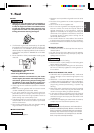
INSTALLING CUTTING
ATTACHMENT GUARD
•Attach the cutting
attachment guard with the
bolts provided to the shaft.
INSTALLING BLADE
1. Put the angled bar(1) into
the side holes of the inner
holder and the angle
transmission.
2.
Remove the nut (Lefthanded)
and the outer holder(3) from
the gearshaft.
3. Put the blade onto the inner
holder(2). Make the marked
side face the holder.
4. Put the outer holder(3) onto
the gearshaft making the
recessed side face the
blade.
5. Fasten the blade by the nut
and the cover(4).
INSTALLING LINE HEAD
1. While locking the gear shaft by inserting the supplied
tool into the upper holder on the angle transmission,
loosen and remove the nut (left-handed).
2. Detach the cover(1), fit the line head assembly to the
gear shaft. Hand tighten it securely.
INSTALLING CUTTING
ATTACHMENT GUARD
FOR LINE HEAD
• When using line head, make
sure to attach the guard
skirt.
BALANCE UNIT
1. Put on strap and attach unit
to strap.
2. Slide clamp up or down un-
til unit balances with head
aparting from the ground
when using it.
(1)