


036-21335-002-A-1102
14 Unitary Products Group
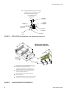
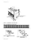
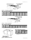
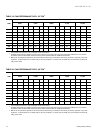
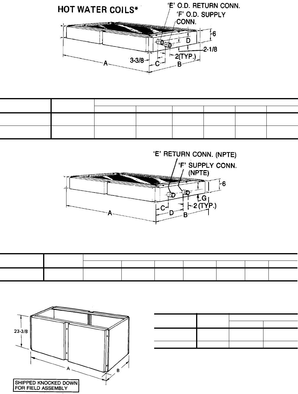
FIGURE 13: HOT WATER COIL DIMENSIONS
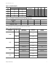
TABLE 14: HOT WATER COIL DIMENSIONS
COIL
MODEL
UNIT
MODEL
DIMENSIONS
ABCDEF
1HW0406
LA300
LB360
100-1/8 37-7/8 6-3/4 3-7/8 1-3/8 1-3/8
1HW0407
LB480
LB600
103-1/8 45-1/4 6-1/2 4 1-5/8 1-5/8
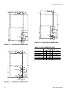
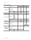
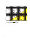
FIGURE 14: STEAM COIL DIMENSIONS
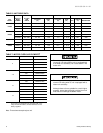
TABLE 15: STEAM COIL DIMENSIONS
1
COIL
MODEL
UNIT
MODEL
DIMENSIONS
A BCDEFG
1NF0454
LA300
LB360
100-1/8 37-7/8 4-3/8 18-3/8 1-1/2 2 2-1/2
1.
Coils are field-installed between the evaporator coil and the blower section of the unit.
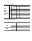
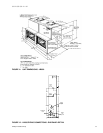
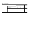
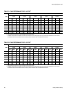
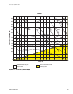
FIGURE 15: BASE SECTION DIMENSIONS
TABLE16:BASESECTIONSDIMENSIONS
1
1.
Ventilation air can be brought into the unit through the
base section providing the base section is fully insu-
latedinthefield.
BASE
MODEL
UNIT
MODEL
DIMENSIONS
AB
1BS0406
LA300
LB360
100-1/8 37-7/8
1BS0407 LB480 103-1/8 45-1/4