


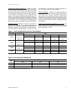
036-21335-002-A-1102
6 Unitary Products Group
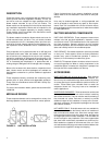
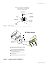
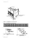
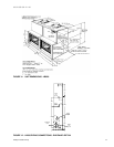
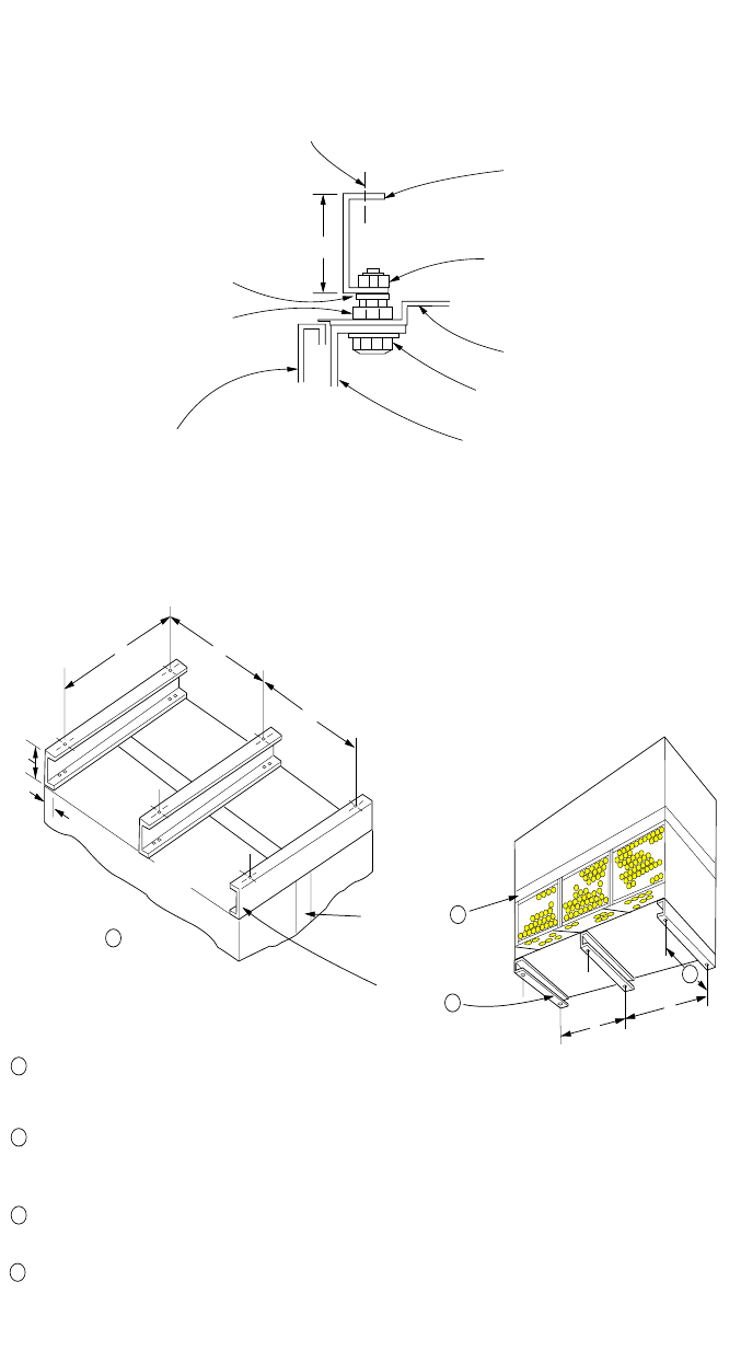
FIGURE 3 : DETAILS FOR SECURING BOTTOM MOUNTING SUPPORTS
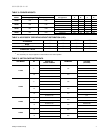
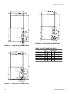
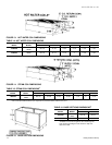
FIGURE 4 : LA300/LB360 WEIGHT DISTRIBUTION
3
NOTE: The following illustration shows how the channels
should be secured to the unit using the hardware
provided with the suspension accessory.
(2) 9/16 HOLES FOR 1/2
HANGER RODS
SUSPENSION
CHANNEL
5/16 NUT,
LOCKWASHER,
FLATWASHER
UNIT PANEL
5/16 BOLT,
FLAT-WASHER
UNIT ANGLE
SIDE
PANEL
5/16 NUT,
FLATWASHER
3/8 NUT (USED
AS SPACER)
AX
3
1-1/2
EVAP. C OIL
S ECTION
BLOWER
S ECTION
HORIZONTAL
LE U360 OR 480
UNIT S US PE NDE D
FROM ABOVE
HE ATING C OIL
2
SUSPENSION
ANGLES
1
BLOWER
S ECTION
EVAP.
COIL
S ECTION
CX
1
2
3
3
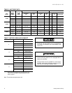
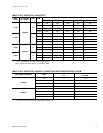
The s ame channels can be used in either position. W hen used to
support at vertical unit, these channels s hould be cut to match the
bottom dimension of the evaporator coil section.
The suspension channels have two sets of mounting holes to
accommodate horizontal units with or without a heating coil. O n
a horizontal unit without a heating coil, the suspension channels
will extend 3" beyond both ends of the unit.
The same channels can be used to s upport a horizontal, floor-
mounted unit from below.
4
After these bottom channels are cut per Note 1, a new hole will have
to be drilled at the cut end if the unit is to be mounted on isolators.
4
VERTICAL LA300, LB360, LB480
UNIT SUPPORTED FROM BELOW
D
B
C
A
D
C
B
A
AX
BX
BX
BX
BX