


036-21335-002-A-1102
18 Unitary Products Group
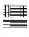
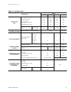
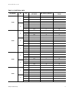
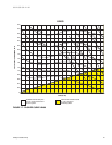
TABLE 19: FAN PERFORMANCE DATA - 25 TON
1
RPM
CFM
8,000 9,000 10,000 11,000 12,000
SP
2
BHP
3
K
W
SP
2
BHP
3
K
W
SP
2
BHP
3
K
W
SP
2
BHP
3
K
W
SP
2
BHP
3
K
W
600 - - - 0.30 2.5 2.3 0.20 3.1 2.9 0.02 3.6 3.4 - - -
635 0.56 2.4 2.3 0.43 2.7 2.6 0.31 3.3 3.1 0.13 3.8 3.5 - - -
700 0.80 3.0 2.8 0.68 3.3 3.1 0.54 3.7 3.5 0.38 4.2 3.9 0.20 4.8 4.5
775 1.12 3.7 3.4 1.00 4.0 3.7 0.85 4.4 4.1 0.70 4.8 4.5 0.54 5.3 5.0
800 1.23 3.9 3.7 1.11 4.3 4.0 0.97 4.7 4.4 0.82 5.1 4.8 0.66 5.6 5.2
875 1.60 4.8 4.5 1.48 5.1 4.8 1.34 5.6 5.2 1.19 6.0 5.7 1.04 6.6 6.2
900 1.73 5.1 4.8 1.61 5.5 5.1 1.47 5.9 5.5 1.33 6.4 6.0 1.17 7.0 6.5
940 1.95 5.6 5.2 1.82 6.0 5.6 1.70 6.5 6.1 - - - - - -
1.
Unit resistance is based on a dry evaporator coil and clean filters.
2.
Available static pressure in IWG to overcome the resistance of the duct system and any accessories added to the unit. Refer to
the blower motor and drive table and the accessory static resistance table for additional information.
3.
Motors can be selected to operate into the service factor because they are located in the moving air stream, upstream of any heat-
ing device. units with steam or hot water coils are the only exception. On these units, the BHP must not exceed the nominal HP
rating of the motor.
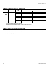
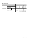
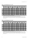
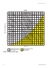
TABLE 20: FAN PERFORMANCE DATA - 30 TON
1
RPM
CFM
10,000 11,000 12,000 13,000 14,000
SP
2
BHP
3
K
W
SP
2
BHP
3
K
W
SP
2
BHP
3
K
W
SP
2
BHP
3
K
W
SP
2
BHP
3
K
W
600 0.20 3.1 2.9 0.02 3.6 3.4 - - - - - - - - -
635 0.31 3.3 3.1 0.13 3.8 3.5 - - - - - - - - -
700 0.54 3.7 3.5 0.38 4.2 3.9 0.20 4.8 4.5 0.03 5.3 5.0 - - -
775 0.85 4.4 4.1 0.70 4.8 4.5 0.54 5.3 5.0 0.39 5.8 5.5 0.20 6.4 6.0
800 0.97 4.7 4.4 0.82 5.1 4.8 0.66 5.6 5.2 0.52 6.1 5.7 0.35 6.7 6.3
875 1.34 5.6 5.2 1.19 6.0 5.7 1.04 6.6 6.2 0.93 7.1 6.6 0.77 7.7 7.2
900 1.47 5.9 5.5 1.33 6.4 6.0 1.17 7.0 6.5 1.07 7.5 7.0 0.90 8.2 7.6
940 1.70 6.5 6.1 1.55 7.0 6.6 1.40 7.7 7.2 1.31 8.3 7.8 1.09 9.0 8.4
1.
Unit resistance is based on a dry evaporator coil and clean filters.
2.
Available static pressure in IWG to overcome the resistance of the duct system and any accessories added to the unit. Refer to
the blower motor and drive table and the accessory static resistance table for additional information.
3.
Motors can be selected to operate into the service factor because they are located in the moving air stream, upstream of any heat-
ing device. units with steam or hot water coils are the only exception. On these units, the BHP must not exceed the nominal HP
rating of the motor.