


4
SETUP AND ADJUSTMENTS FORSETUP AND ADJUSTMENTS FOR
SETUP AND ADJUSTMENTS FORSETUP AND ADJUSTMENTS FOR
SETUP AND ADJUSTMENTS FOR
YAZOO/KEES KUTTER 32", 36" AND 48" COMMERCIAL MOWERSYAZOO/KEES KUTTER 32", 36" AND 48" COMMERCIAL MOWERS
YAZOO/KEES KUTTER 32", 36" AND 48" COMMERCIAL MOWERSYAZOO/KEES KUTTER 32", 36" AND 48" COMMERCIAL MOWERS
YAZOO/KEES KUTTER 32", 36" AND 48" COMMERCIAL MOWERS
FRONT CASTER WHEELSFRONT CASTER WHEELS
FRONT CASTER WHEELSFRONT CASTER WHEELS
FRONT CASTER WHEELS
1. Mount front caster wheel assemblies. Installation
includes fastening casters to front of the cutter deck
using 3/8 x 1" hex head capscrews.
FUEL TANKFUEL TANK
FUEL TANKFUEL TANK
FUEL TANK
1. Mount fuel tank to tank support. Secure with the two
tank straps, four 1/4" bolts, and four 1/4" nuts. Tighten
until snug, but do not over tighten or crush the tank.
HANDLE ASSEMBLYHANDLE ASSEMBLY
HANDLE ASSEMBLYHANDLE ASSEMBLY
HANDLE ASSEMBLY
1. Align the upper mounting holes in handle with the
upper hole in the tank support.
2. Install two 3/8" x 1" screws through matched holes and
loosely install 3/8" nuts.
3. Align the lower holes and install hardware as above,
tighten upper and lower hardware.
LINKAGE INSTALLATIONLINKAGE INSTALLATION
LINKAGE INSTALLATIONLINKAGE INSTALLATION
LINKAGE INSTALLATION
1. Install traction linkage to swivels in bellcrank mounted
to the tank support on each side of the mower. Traction
linkages are located on the upper handle, fastened to
the traction levers. To fasten linkage to swivel, first
disconnect linkage from traction levers, then screw
linkage into swivel. Reassemble linkage into traction
lever.
2. Install shifter to transmission with 1/4" x 1" screws.
The shifter is located in the inner box and hardware is
preassembled into the bracket on the transmission.
3. Install blade control rod into the bellcrank on the left
side of the tank support. Secure rod with ring type
retainer.
4. Refer to the section of this manual on adjustments for
the proper adjustment of the linkages you are
installing.The linkages were set at the factory but must
be checked before operating mower to insure of the
proper setting. Always check 100% of the adjustments
before you operate the mower.
5. Connect the two halves of the wiring harness together.
The four prong connectors have a locking tab that
shows which way to line them up and guarantees that
they are connected properly when the lock snaps.
6. Install the chute deflector to the side of the mower
deck. Bolt it into place using the two 5/16" x 1" screws and
nuts preassembled into the mounting tabs on the deck.
Tighten the screws very securely with the chute
completely covering the discharge opening and tight
against the side of deck.
THROTTLE INSTALLATIONTHROTTLE INSTALLATION
THROTTLE INSTALLATIONTHROTTLE INSTALLATION
THROTTLE INSTALLATION
1. Connect the throttle cable end to the throttle
mechanism on engine, leaving the cable clamp loose.
Push throttle lever on console completely forward. Then
pull the cable through the clamp on engine and tighten
the cable clamp. Move the throttle lever back and forth
to ensure proper installation.
GAS LINE INSTALLATIONGAS LINE INSTALLATION
GAS LINE INSTALLATIONGAS LINE INSTALLATION
GAS LINE INSTALLATION
1. The gas line is factory installed on the engine. Attach
loose end to fuel tank hose barb and secure with hose
clamp.
POSITIONING THE FRONT CASTER SPACERSPOSITIONING THE FRONT CASTER SPACERS
POSITIONING THE FRONT CASTER SPACERSPOSITIONING THE FRONT CASTER SPACERS
POSITIONING THE FRONT CASTER SPACERS
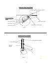
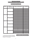
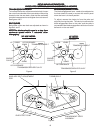
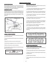
1. Using the cutting height chart, find the correct number
of spacers to be placed under the caster swivel.
2. Remove the lynch pin and washer from the top of
caster and reposition spacers to the desired cutting
height from the chart. See figure # 2
AXLE HEIGHT ADJUSTMENTAXLE HEIGHT ADJUSTMENT
AXLE HEIGHT ADJUSTMENTAXLE HEIGHT ADJUSTMENT
AXLE HEIGHT ADJUSTMENT
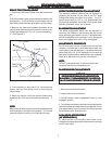
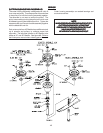
1.To adjust rear axle, stop engine and place drive
levers in the neutral lock position, remove spark plug
wire.
2. Remove lower belt shield from underside of rear deck
for better access to axle adjustment bolts.
3. Loosen axle pivot bolts and axle adjustment bolts.
See figure # 1.
4. Place a jack under center of rear deck raise the jack
slightly so axle adjustment bolts may be removed.
5. With the jack raise or lower the rear deck to the desired
position using the chart to ensure proper height. Reinstall
the axle adjustment bolts and tighten.
A tapered punch may be used to help align the holes.
See figure #1.
It may be necessary to readjust drive and brake linkages.
NOTE:
NOTE:
To achive the best quality cut, the blades should be
level with the ground or slightly tipped forward.