


6
Attaching Chute Directional Control
For packaging purposes, the two-piece chute
directional control was attached to the snow thrower on
the two ends, but was kept loose at the middle.
Assemble as follows:
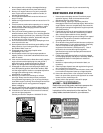
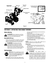
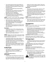
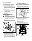
• Remove the hairpin clip from the chute directional
control. Align holes on the upper and lower pieces
of the chute directional control before reinserting
the hairpin clip. See Figure 4.
Figure 4
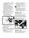
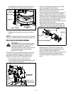
• If not already attached, slip the cables that run from
the handle panel to the chute into the cable guide
located on top of the engine. See Figure 5.
Figure 5
• Unwrap the headlight wire which is attached to the
headlight, beneath the handle panel. Wind the
headlight wire around the right handle until excess
slack is removed.
• Plug the headlight wire into the wire lead found on
the right side of the engine, beneath the fuel tank.
Chute Clean-Out Tool
• This tool is fastened with a cable tie to the rear of
the auger housing for shipping purposes. Cut the
cable tie and remove tool before operating the
snow thrower.
Final Adjustments
Traction Control and Shift Lever Adjustment
To check the adjustment of the traction control and shift
lever, proceed as follows:
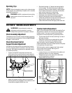
• Move the shift lever into sixth (6) position.
a. With the traction control (refer to Figure 6)
released, gently push the snow thrower
forward, then pull it back. Disregarding the
overall weight of the snow thrower, the
machine should otherwise move freely.
b. Engage the traction control, and attempt to
move the machine both forward and
rearward. You should experience resistance
as the wheels should not be turning.
• Move the shift lever into the fast reverse (R2)
position and repeat the previous steps (a & b).
If you experienced resistance either when repositioning
the shift lever from 6 to R2 or when attempting to move
the machine forward or rearward with the traction
control released, your snow thrower’s traction control is
in need of adjustment and you should NOT operate the
machine before completing the adjustment as follows:
• Loosen the jam nut on the traction control cable
and UNTHREAD the cable one full turn.
• Recheck the adjustment.
• Retighten the jam nut to secure the cable when
correct adjustment is reached.
If the machine can be moved freely both forward and
rearward when the traction control fully depressed,
proceed as follows:
• Loosen the jam nut on the traction drive cable and
THREAD the cable in one full turn.
• Recheck the adjustment and repeat as necessary.
• Retighten the jam nut to secure the cable when
correct adjustment is reached.
If you are unsure that you have reached the correct
adjustment, refer to Traction Control Adjustment on page.
11 of this manual.
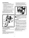
Tire Pressure Adjustment
The tires are over-inflated for shipping purposes.
Check tire pressure and reduce to between 15 psi and
20 psi.
NOTE: If the tire pressure is not equal in both tires,
the unit may pull to one side or the other.
Hairpin Clip
Cable Guide