


14
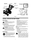
Shave Plate and Skid Shoes
The shave plate and skid shoes on the bottom of the
snow thrower are subject to wear. They should be
checked periodically and replaced when necessary. To
remove the skid shoes, proceed as follows:
• Remove the four carriage bolts, bell washers and
hex nuts which attach them to the snow thrower.
Reassemble new skid shoes with the four carriage
bolts, bell washers (cupped side goes against skid
shoes) and hex nuts. Make certain the skid shoes
are adjusted to be level.
• To remove shave plate, remove the carriage bolts,
belleville washers and hex nuts which attach it to
the snow thrower housing.
• Reassemble new shave plate, making sure heads
of the carriage bolts are to the inside of the housing.
Tighten securely.
Belt Removal And Replacement
WARNING: Disconnect spark plug wire
and ground it against the engine to prevent
unintended starting. Drain fuel into an
approved container or place a piece of plastic
film underneath the gas cap to prevent
gasoline from leaking.
Auger Belt
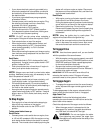
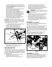
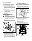
• Remove the plastic belt cover by removing the two
self-tapping screws. See Figure 15.
Figure 15
• Drain the gasoline from the snow thrower.
• Tip the snow thrower forward so that it rests on its
auger housing and remove six self-tapping screws
from the frame cover underneath the snow thrower.
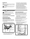
• Roll the belt off the engine pulley. See Figure 16.
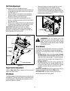
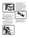
• Unhook the idler spring from the hex bolt on the
auger housing. See Figure 17.
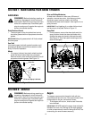
• Back out the stop bolt until the support bracket
rests on the auger pulley. See Figure 18.
NOTE: Loosening the six nuts that connect the frame
to the auger housing may aid in belt removal.
• Lift the auger belt from the auger pulley, and slip
belt between the support bracket and the auger
pulley. See Figure 18. Repeat this step for the front
auger belt.
Figure 16
• Replace the auger drive belt by following
instructions in reverse order.
Drive Belt
• Follow the first four steps of the instructions for
servicing the auger belt.
• Pull idler pulley up, and lift the belt off the engine
pulley and friction wheel disc. See Figure 16.
• Back out the stop bolt until the support bracket
rests on the auger pulley. See Figure 18.
Figure 17
Self-Tapping
Screw
Belt Cover
Auger Pulley
Drive
Belt
Engine
Pulley
Engine
Pulley
Idler
Pulley
Idler
Pulley
Auger
Belt
Friction
Wheel
Support
Bracket
Auger Pulley
Idler Spring
Support
Bracket
Spring
Auger Housing