


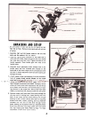
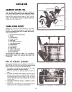
UNPACKING AND SET-UP
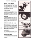
3. Assemble handle panel assembly to the under side of
right and left handle tubes and secure with four slotted
hex head bolts and lock nuts. Tighten all bolts on the
handle assembly. Place handle grips over ends of the
handle tubes.
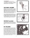
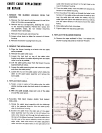
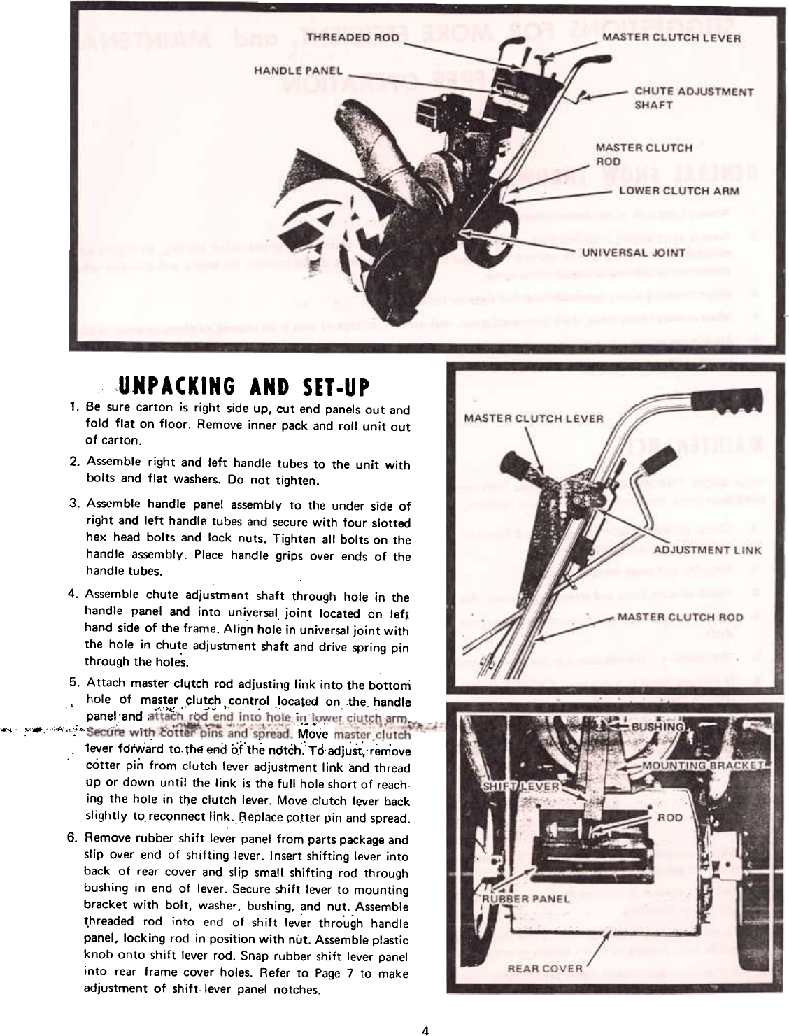
4. Assemble chute adjustment shaft through hole in the
handle panel and into uni";'ersal. joint located on lef!
hand side of the frame. Align hole in universal joint with
the hole in chute adjustment shaft and drive spring pin
through the holes.
5. Attach master cl~tch rod adjusting link into the bottom
hole of master clutch control located on .the. handle"panel'andi~""t(.."'-"';)"."';"
':
" -..'
.'J.
..Move I ..
.1ever forward to. thf! end o.f"the not6h To. adjust:,. remove
cotter pin from clutch lever adjustment link and thread
op or down until the link is the full hole short of reach-
ing the hole in tl)e clutch lever. Move .clutch lever back
slightly to. rec9nnect link.. Replace Go.tter pin and spread.
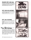
6. Remove rubber shift lever panel from parts package and
slip over end of shifting lever. I nsert shifting lever into
back of rear cover and slip small shifting rod through
bushing in end of lever. Secure shift lever to mounting
bracket with bolt, washer, bushing, and nut. Assemble
t.hreaded rod into end of shift lever through handle
panel, locking rod in position with nut. Assemble plastic
knob onto shift lever rod. Snap rubber shift lever panel
into rear frame cover holes. Refer to Page 7 to make
adjustment of shift lever panel no~ches.
-, ;"'*-""""',"'"
4
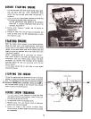
1. Be sure carton is right side UP. cut end panels out and
fold flat on floor. Remove inner pack and roll unit out
of carton.2.
Assemble right and left handle tubes to the unit with
bolts and flat washers. Do not tighten.