


5
SECTION 2: ASSEMBLING YOUR TILLER
IMPORTANT:
This unit is shipped without gasoline or oil
in the engine. Be certain to service engine with gasoline
and oil as instructed in the separate engine manual
before operating your mower.
NOTE: Reference to right or left hand side of the tiller is
observed from the operating position.
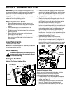
Removing Unit From Carton
• Remove staples, break glue on top flaps, or cut
tape at carton end and peel along top flap to open
carton.
• Remove loose parts if included with unit (i.e.,
operator’s manual, etc.)
• Cut along corners, lay carton down flat, and remove
packing material.
• Roll or slide unit out of carton and check carton
thoroughly for loose parts.
• Extend control cables to the rear of the tiller and lay
them on the floor. Be careful not to bend or kink
control cables.
Loose Parts In Carton
Tailpiece and Depth Stake
NOTE: All hardware needed for assembly is attached
to the loose parts or the tiller.
Before Assembly
WARNING: Disconnect the spark plug wire
and ground it against the engine to prevent
unintended starting.
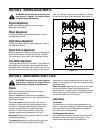
Setting Up Your Tiller
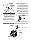
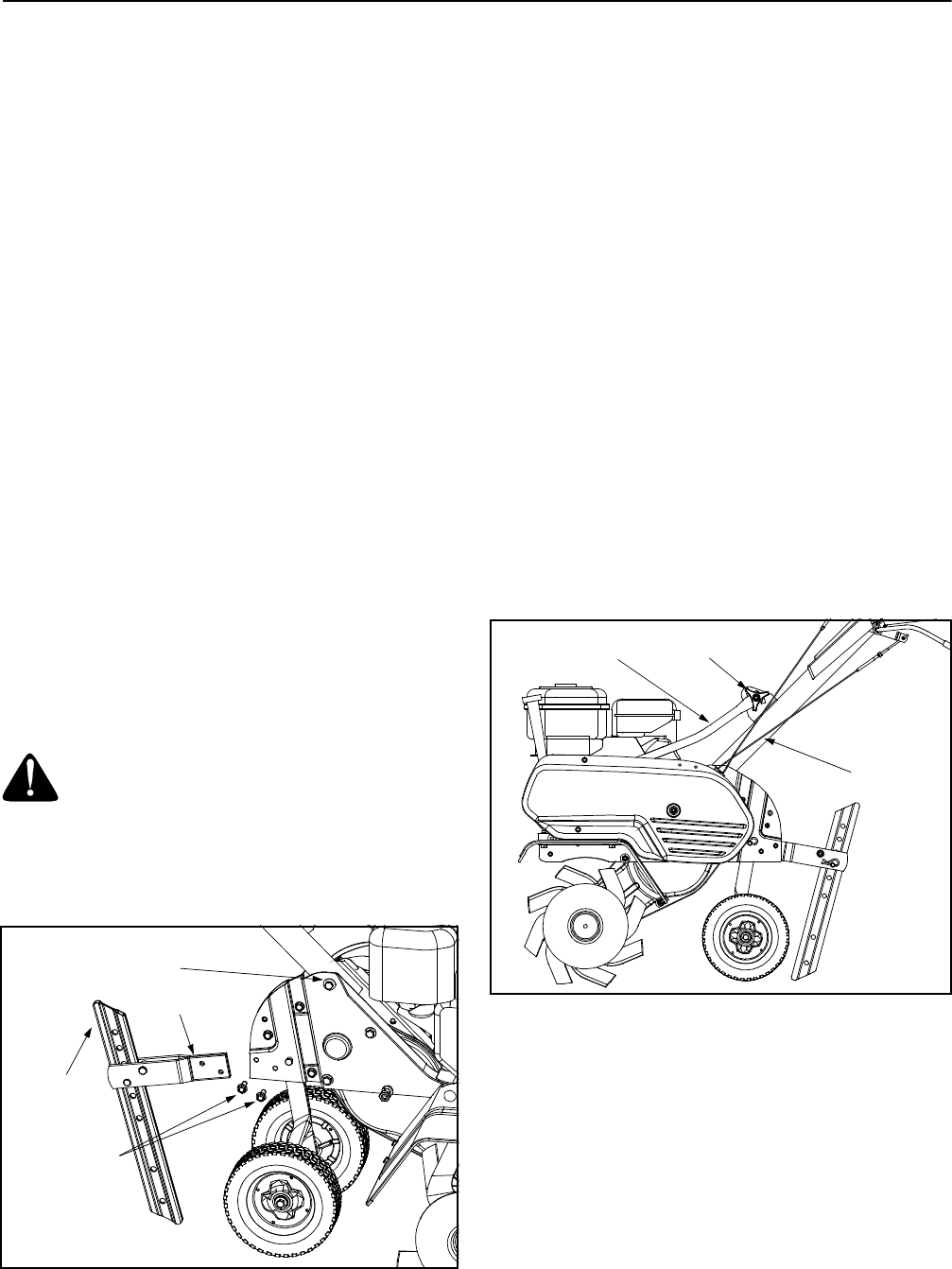
Attaching The Tailpiece And Depth Stake
Figure 1
• Remove the two self-tapping screws on the frame
and slide the tailpiece into the frame, with the lower
hole in the tailpiece toward the front. See Figure 1.
• Secure tailpiece with screws just removed.
Attaching The Handle Assembly
• Remove the hex bolt and cupped washer from the
top right side of the frame halves. Hold the cable
guide bracket on the left side of the frame as it will
fall when the bolt is removed. See Figure 1.
• Insert the handle assembly between the two frame
halves and insert the hex bolt just removed through
the frame halves, handle assembly, and into the
cable guide bracket (notch in cable bracket goes
over the flange on the frame).Tighten securely.
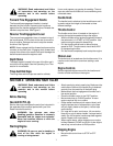
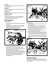
• Remove the handle knob and hardware from the
handle brace. Insert the carriage screw through the
welded bracket on the handle and into the end of
the handle brace. See Figure 2.
• Secure with bell washer and handle knob.
• Select one of the three handle height positions
(three notches in welded bracket), and tighten the
handle knob to secure the handle in desired
position. Make certain the carriage screw is seated
securely into one of the three positions provided.
Figure 2
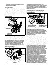
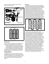
Attaching Clutch Control Cables
Attach the end of the forward clutch cable, which is
located in the rear of the tiller, to the bracket
underneath the handle assembly as follows:
• Loosen the hex nut on the threaded rod near the
end of the cable and move it up the rod as far as it
will go. See Figure 3.
• Unthread the rod from the rest of the cable and
hook the “Z” end of the rod into the bracket
underneath the handle assembly from the right
hand side.
Tailpiece
Self-Tapping
Screws
Depth
Stake
Hex Nut and
Cupped Washer
Handle
Knob
Handle
Brace
Handle
Assembly