


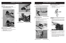
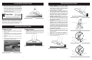


NOTE: The only assembly required for your trimmer is to
install the edge guide wheel, debris shield and adjust the
assist handle.
EDGE GUIDE WHEEL INSTALLATION
1. Position the edge guide wheel (A) to the front of the
motor housing as shown in Fig. 1.
2. Tighten the wing nut (B) firmly. (Fig. 2)
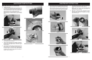
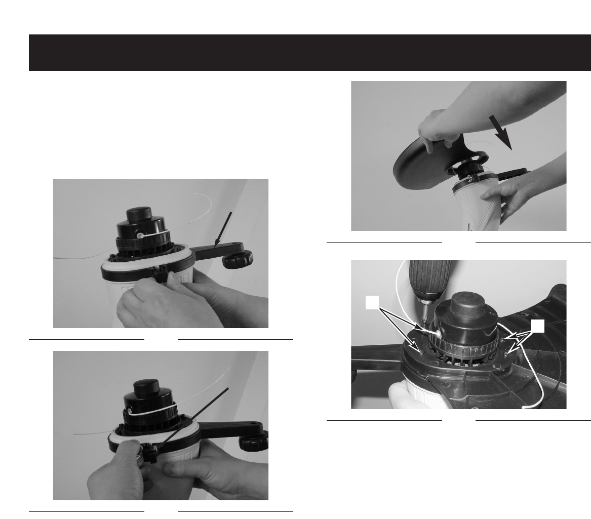
DEBRIS SHIELD INSTALLATION
1.
Position the motor housing with string head car
rier
facing up. (Fig. 3)
2. Slide debris shield over motor housing.
3.
Secur
e it with 4 screws (C). (Fig. 4)
8
7
ASSEMBLY INSTRUCTIONS
Fig. 1
A
Fig. 2
B
Fig. 3
Fig. 4
C
C
ADJUST SHAFT LENGTH
1. Grip shaft firmly.
2. Push shaft release button (A) and move motor hous-
ing f
orward or backward to desired length. (Fig. 5)
NOTE: Shaft may be adjusted in trimming or edging mode.
EDGING CONVERSION
1. Grip shaft firmly.
2. Push edge button (B) and rotate handle assembly
until an audible click is heard. (Fig. 6 & Fig. 7)
3. Adjust assist handle as required.
ADJUST THE ASSIST HANDLE
NOTE: The assist handle is attached to the shaft but has
been turned under for packing
1.
Loosen adjustment knob and rotate handle to the top
of shaft (Fig. 8).
2.
Tighten adjustment knob securely.
STARTING
1. Before starting the grass-trimmer for the first time,
check that the nylon line touch or pass over the line-
cutting blade. If they are not long enough, press the
bump knob and, at the same time, pull the nylon line.
(Fig. 9).
2. Connect the correct extension cord to the string trim-
mer power cord per the instructions in Section 5-1
Connect the cord.
3.
Mak
e sure the length of g
r
ass tr
immer and position of
assist handle is most applicable before use, adjust the
length of g
r
ass trimmer by pressing the shaft adjust-
ment b
utton, adjust the height of assist handle b
y
loosening the adjustment knob.
ADJUSTMENT INSTRUCTIONS
Fig. 5
A
Fig. 6
B
Fig. 7
Fig. 8
Fig. 9