


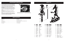


MODEL NO. . . . . . . . . . . . . . . . . . . . . . . . . . . . . . . . . . . . . . . . .MTD1400K
Input . . . . . . . . . . . . . . . . . . . . . . . . . . . . . . . . . . . . . . . . . . . . . .120V~, 60Hz, 14Amp
Hopper Size . . . . . . . . . . . . . . . . . . . . . . . . . . . . . . . . . . . . . . . . .394x270x200mm (15-1/2”x10-5/8”x7-7/8”)
No Load Speed . . . . . . . . . . . . . . . . . . . . . . . . . . . . . . . . . . . . . .3 300 min
-1
/RPM
Net Weight . . . . . . . . . . . . . . . . . . . . . . . . . . . . . . . . . . . . . . . . . .77 Lbs (35 Kg)
SPECIFICATIONS
11 12
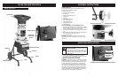
PARTS LIST
3939
4545
4444
1313
5151
5757
5656
6666
6767
6868
4040
1616
1616
1616
1818
1010
1
515
1818
5252
4646
4747
4848
5
353
6
161
6464
7070
7171
2525
2222
2
020
1818
1919
2
121
1212
1111
1414
6262
2424
55
6969
6565
6060
5959
5858
5050
4343
4
141
3535
3737
1717
99
44
66
77
7
7
77
1
313
5454
6363
2323
2
626
5555
4949
4242
3636
3838
3434
1
818
88
55
33
3
3
22
22
11
4141
1313
5
5
2727
2828
2929
3030
3131
3232
3
333
No.
1
2
3
4
5
6
7
8
9
10
11
12
13
14
15
16
17
18
19
20
21
22
23
24
Parts No.
6266-200103
6200-200101
6134-200101
6024-200101
6WSB-08
6014-200101
6STBBM05-15
6270-200111
6263-200102
6158-200101
6134-200102
6SDABB04-20
6WFZ-08
6CE-06
6SDAZ-04-10
6WFZ-04
6263-200101
6NAZ-04
6WSB-04
6262-200106
6SDAZ-05-55
6059-200101
6NAZ-05
6SXDZ-10-35
Description
TOP HOPPER
SCREW
KNOB
RESTRAINNIG SPRING
SPRING WASHER
WASHER
SCREW
BODY
DUST PLATE
CUTTER CLAMP
KNOB
SCREW
WASHER
E RING
SCREW
WASHER
DUST PLATE
NUT
SPRING WASHER
RESTRAINING COVER
SCREW
BRACKET TUBE
NUT
SCREW
No.
37
38
39
40
41
42
43
44
45
46
47
48
25
26
27
28
29
30
31
32
33
34
35
36
Parts No.
6207-200102
6036-200101
6262-200101
6022-200001
6SDAZ-04-08
6262-200001
6010-200004
6010-200005
6099-200103
6SDABB04-14
6043-840001
6WFZ-06
6WSB-10
6158-200002
6156-200001
6250-200003
6267-200001
6200-200002
6250-200001
6268-200101
6124-200101
6200-200001
6WDB-08
6200-200102
Description
BRACKET CLAMP
SWITCH HOLDER
SWITCH COVER
CUT-OUT SWITCH
SCREW
SWITCH COVER
INTERNAL WIRE I
INTERNAL WIRE II
MOTOR ASS'Y
SCREW
CORD CLAMP
WASHER
SPRING WASHER
CUTTER CLAMP
SQUARE BUSH
V-CUTTER
V-CUTTER BASE
SCREW M10x10
CUTTER (BLADE)
CUTTER BASE
CUTTER BUSH
SCREW M8x18
SPRING WASHER
SCREW
No.
49
50
51
52
53
54
55
56
57
58
59
60
61
62
63
64
65
66
67
68
69
70
Parts No.
6SDAZ-06-12
6086-200104
6010-200006
6272-200002
6022-200002
6199-200002
6100-200101
6011-200005
6111-200101
6NAZ-08
6027-200101
6111-200102
6004-200104
6087-200102
6SRCB-08-16
6004-200103
6SRCB-08-40
6228-200013
6WFZ-12
6PB-26
6067-200007
6SJABB03-10
Description
SCREW
MOTOR COVER
INTERNAL WIRE
THERMOSTAT
ON/OFF SWITCH
CORD GUARD
PLATE
POWER CORD
STRENGTEN SHAFT
NUT
FRAME GASKET
WHEEL SHAFT
LEFT HOLDER
CONNECTING TUBE
SCREW
RIGHT HOLDER
SCREW
WHEEL
WASHER
PIN
WHEEL COVER
SCREW
71 6042-200001 WRENCH
72 6188-200402 MARTERIAL PUSH STICK
73 6280-200001 STARP BAG HOLD
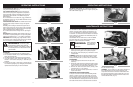
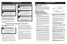
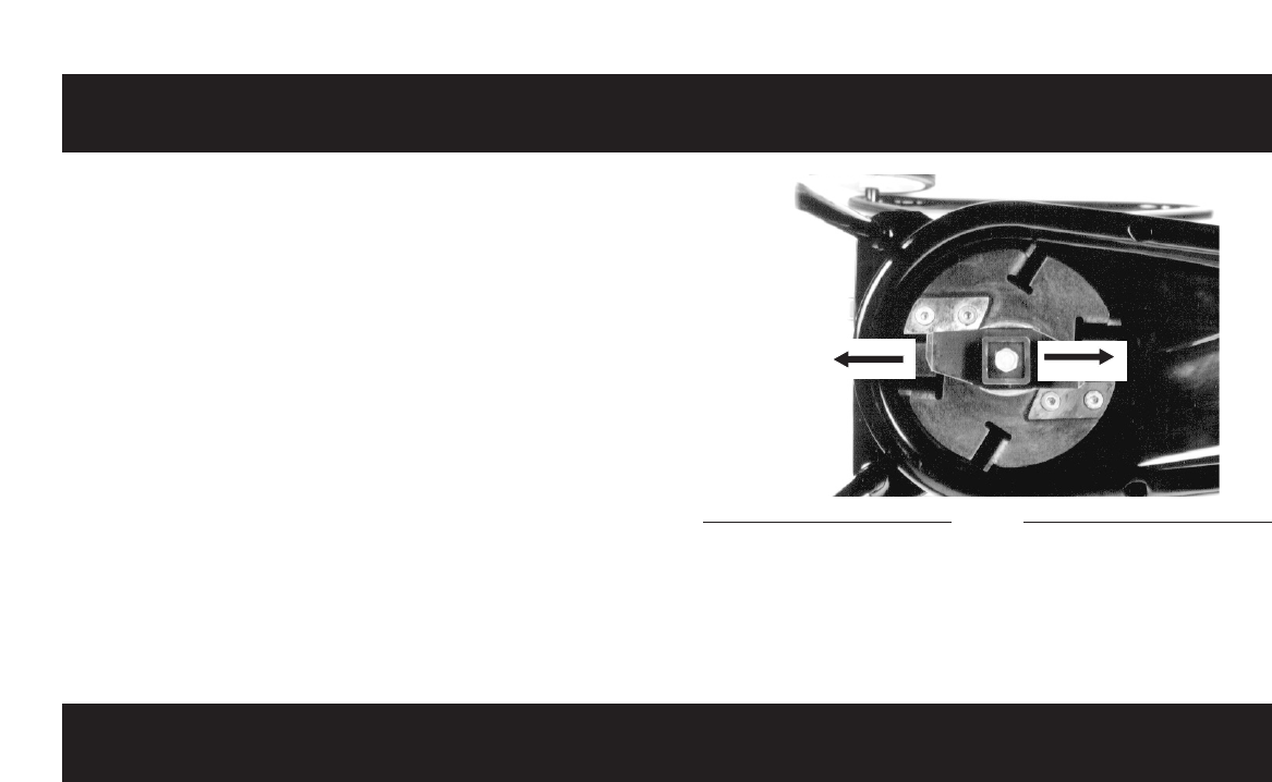
MAINTENANCE INSTRUCTIONS
Before replacing the top cover assembly ensure that the
V-cutter is positioned as shown in (Fig. 13) Replace the
top cover assembly and secure tightly the caging knobs.
If caging Knobs are not tight the motor will not start due
to the motor lock out switch not bein activated.
CLEANING After use, always wipe clean the outside of
the Shredder to remove any build up of material with a
damp cloth. Clean the inside of the cutting chamber and
remove any left over material, Do not hose down with
water.
IMPORTANT: Before replacing top cover assembly
ensure that the V-cutter is positioned as shown in (Fig.
13).
Replace the top cover assembly together with the top
cover screw knob ensuring this is tight. If the top cover
screw knob is not tight the motor will not start due to the
motor lock out switch not being activated.
Fig. 13