


7
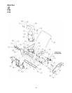
INSTALLING THE CHUTE CRANK
(Models 150 thru 152 and model 140 with Optional Extended Chute Crank only.)
On some units, the chute crank can be installed and secured from the top side of the snow thrower. Other units
are equipped with an adaptor that requires the assembler to tip the unit forward on the auger housing in order to
secure the crank from the underside.
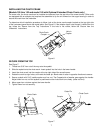
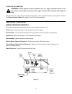
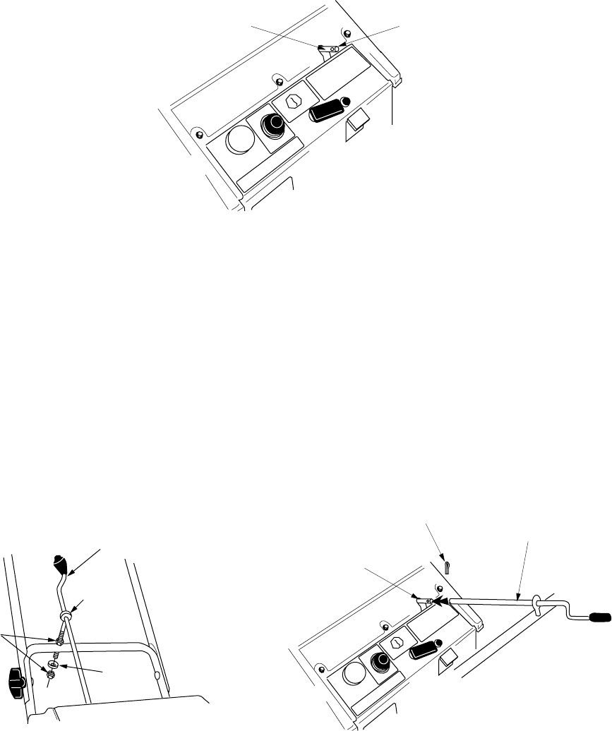
To determine which installation procedure to follow, look at the chute crank coupler located on the top right side
of the instrument panel above the model plate. See Figure 6. If the adaptor has a hole through it visible from the
top, follow the ”Secure from the Top” instructions. If the hole is not visible, follow the “Secure from the
Underside” instructions.
Figure 6
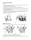
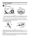
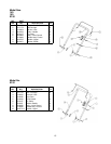
SECURE FROM THE TOP.
See Figure 7.
1. Thread one 5/16” hex nut all the way onto the eyebolt.
2. Slide the eyebolt onto the chute crank. Insert eyebolt into the hole in the lower handle.
3. Insert the chute crank into the coupler at the top right side of the snow thrower.
4. Rotate the crank to align holes, and insert the cotter pin. Bend ends of cotter in opposite directions to secure.
5. Secure eyebolt with 5/16” saddle washer and hex nut. The Cupped side of washer goes against the handle.
Adjust lower hex nut until the eyebolt is positioned so the chute crank turns freely. (does not bind)
6. Move upper hex nut down against the lower handle.
7. Tighten lower hex nut securely.
Figure 7
Chute Crank
Coupler
Hole in
Coupler
Hex
Nuts
Eye Bolt
Chute Crank
Saddle
Washer
Cotter Pin
Chute Crank
Coupler