


Connecting the DC Cables
975-0128-01-01 3–13
Connecting the DC Cables
Consult Figure 3-1, “Configuration for Normal Loads” on page 3–2, or
Figure 3-2, “Configuration for Heavy Loads” on page 3–2 for additional
details that are specific to your installation.
To make the DC connections:
1. Cut the cables to the correct length with enough insulation stripped
off so you can properly install the type of terminals you will be using.
The terminals on the DC end are designed to fit up to 500 MCM
crimp-on ring terminals (either AMP or ILSCO) or box connectors.
2. Attach the connectors to both cables.
If using compression lugs, attach the terminals to both cables using
the crimp tool recommended by the manufacturer of the ring
terminals. There must be no stray wire strands protruding from
the terminal. If using box lugs, attach the lug to the XPower Inverter
3000 Plus first, then insert the wire and tighten the set screw to the
torque recommended by the lug manufacturer.
3. Route the DC supply cables from the battery bank to the inverter.
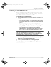
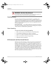
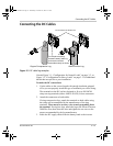
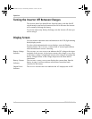
Figure 3-5
DC cable lug examples
Copper Compression Lug
Aluminum Box Lug
Do not remove the terminal nut
Do not place anything
between battery cable lug
and terminal surface.
Assemble exactly as shown.
XPower3000.book Page 13 Wednesday, December 10, 2003 6:52 AM