


Installation
3–12 975-0128-01-01
Grounding Locations
You must connect the chassis ground terminal to a grounding point.
Follow the installation guidelines below. These guidelines assume you are
using the code-compliant DC supply cable and fuse sizes indicated in this
manual. If you are using different sizes, refer to the applicable code for
DC grounding details.
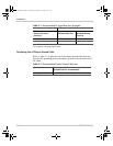
Recreational Vehicle Use 8 AWG copper wire and connect it between
the Chassis Ground lug and the vehicle’s DC grounding point (usually the
vehicle chassis or a dedicated DC ground bus).
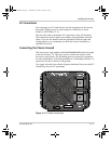
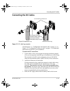
Chassis Ground Lug
To connect the cable to the chassis ground lug:
1. Make sure the inverter’s On/Off switch is in the Off position.
2. Loosen chassis ground lug screw using a screwdriver.
3. Strip 3/8" (9.5 mm) of insulation from one end of the cable.
4. Place one end of the cable into the ground lug.
5. Tighten the chassis ground lug.
DC Disconnects and Over-Current Devices
The DC circuit from the battery to the inverter must be equipped with a
disconnect and over-current device. This usually consists of a circuit
breaker, a “fused-disconnect,” or a separate fuse and DC disconnect. Do
not confuse AC circuit breakers with DC circuit breakers. They are not
interchangeable. The rating of the fuse or breaker must be matched to the
size of cables used in accordance with the applicable installation codes.
The breaker or disconnect switch and fuse should be located as close as
possible to the battery, in the positive cable. Applicable codes may limit
how far the protection can be from the battery.
WARNING: Electrical Shock Hazard
Never operate the inverter without properly connecting the chassis ground. An
electrical shock hazard could result from improper grounding.
XPower3000.book Page 12 Wednesday, December 10, 2003 6:52 AM