


page 12
only when the hydraulic motor supports are
in the rearward position and vice versa.
See the section above, "Hydraulic Motor
Support Adjustment".
Use the higher holes for the anti-tip roller for
motor supports in highest holes in tractor
frame, setting "a" above.
Use the lower holes for the anti-tip roller for
motor supports in middle or lowest holes
in tractor frame, settings "b" or "c" above.
Adjust the front caster arms at their respec-
tive support brackets equally in one of the
seven settings up or down 0.25" each
through a 1.5" total range.
a. This should be done with two shims (or
"C" spacers) on the bottom and one
shim on the top of the caster support
arm.
b. The front-to-rear leveling of the blades
should be between level (preferred)
to .25" lower at the front of the blades
but never higher at the front.
c. Use the lowest holes in tractor frame
for heights of 3.25" - 4.5".
Temporary Height-of-Cut Adjustment: using
the caster shims (or "C" spacers) you can
adjust the blades downward temporarily .5"
or 1" below the original coarse setting as
described above. This assumes that the
blades are level with two shims (or "C"
spacers) on the bottom and one shim on the
top of the caster support arm. With the
blades level at this assumed starting point,
you should never move all of the shims to the
bottom since that would make the blades
higher at the front.
The angle of attack of the blades should
always be level or lower at the front. This
makes the blade cut the grass only once
and saves fuel and wear on the whole
mower. It also allows more efficient
mowing and grass catching or dispersal.
If you mow in an area of the country
where the lawn is very thick and spongy
you may have to set these two adjust-
ments as they would appear on the grass
and not on a hard surface due to the tires
“floating” up on or “sinking” down into the
lawn.
Fine Adjustment: Adjust the blades equally in
five settings up or down 0.25" each in a 1.25"
total range. The shims on the blade bolts are
moved from under the spindle to the top of the
spindle. If possible, leave at least one shim at
the top and the bottom of the spindle shaft.
Using the maximums and minimums of these
methods gives you a total range of 2.75" from
1.75" to 4.5" in eleven distinct settings. The
factory setting is 3" when measured to a hard
floor surface at the front of the deck.
Belt Tension Adjustment
The pump drive belt is self-adjusting, and nor-
mally requires no adjustment, just replacement. It
is spring loaded to prevent strain on the pump
bearings. However, there are three holes for
locating the bolt where the spring attaches for
increasing the spring tension. Factory setting is
the hole to the right side of the mower which is
the least tension. The blade drive belts should
be tightened only so that you can deflect the belt
about 1/2 inch when pushing 8 lbs. with your
thumb. DO NOT OVER TIGHTEN OR THE
SPINDLE AND IDLER BEARINGS WILL WEAR
PREMATURELY OR YOU COULD DAMAGE
THE ENGINE BEARINGS. This adjustment
should be checked at forty (40) hour intervals
except new belts should be checked every four
(4) hours for the first twenty (20) hours. A loose
belt will not cut grass, will run hot and wear
prematurely.
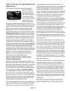
How To Move The Mower If The En-
gine Won’t Start
Rotate both of the manual “dump” valve levers
on the top of each hydraulic pump about 1/2 turn
counterclockwise. Tighten the valves again
before starting the mower again.
How To Bleed Air From The Hydraulic
System
When any of the hydraulic parts are disconnected
or removed or when the oil is changed, air must
be bled from the system. Disconnect the small
hose line from each of the pumps going to the oil
filter. When oil starts to flow without bubbles from
end of hose, plug the hose. When oil starts to flow
without bubbles from the disconnected open port
on the pump, reconnect hose to pump. Set the