


38 Assembly
MAN0506 (Rev. 9/5/2008)
ASSEMBLY
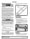
DEALER SET-UP INSTRUCTIONS
Do not allow bystanders in the area when oper-
ating, attaching, removing, assembling, or servic-
ing equipment.
Do not handle knives with bare hands. Careless
or improper handling may result in serious injury.
Keep hands and body away from pressurized
lines. Use paper or cardboard, not hands or other
body parts to check for leaks. Wear safety goggles.
Hydraulic fluid under pressure can easily penetrate
skin and will cause serious injury or death.
Make sure that all operating and service person-
nel know that if hydraulic fluid penetrates skin, it
must be surgically removed as soon as possible by
a doctor familiar with this form of injury or gan-
grene, serious injury, or death will result. CON-
TACT A PHYSICIAN IMMEDIATELY IF FLUID
ENTERS SKIN OR EYES. DO NOT DELAY.
Check that all hardware is properly installed.
Always tighten to torque chart specifications
unless instructed otherwise in this manual.
Always wear relatively tight and belted clothing
to avoid getting caught in moving parts. Wear
sturdy, rough-soled work shoes and protective
equipment for eyes, hair, hands, hearing, and head;
and respirator or filter mask where appropriate.
Use a suitable lifting device of sufficient capac-
ity. Use adequate personnel to handle heavy com-
ponents.
1. Open the crate and cartons containing the
attaching components and mounting hardware.
2. Use the packing list to check that all parts have
been shipped.
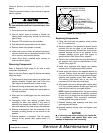
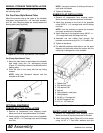
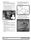
For Some Models Shipped on End
Units that stand on their aft ends during shipping have
a dipstick shipping plug installed in the gearbox dipstick
tube to prevent leakage during shipping.
NOTICE
■
For units shipped on aft end, the dipstick ship-
ping plug must be removed before shredder opera-
tion. Replace plug with dipstick in filler tube after
shredder has been removed from truck and leveled.
After the unit has been leveled for a couple of hours,
check oil level and service through the dipstick/filler
tube as required.
Figure 40. Dipstick Shipping Plug Removal
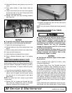
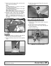
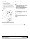
WHEEL ASSEMBLY
1. Raise the rear of the unit.
2. Place safety stands or large blocks under frame.
3. Measure the wheel spacing from the center of the
unit. Mark the frame (rockshaft).
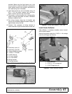
4. Install the wheel assembly to the rockshaft (Figure
41). If equipped with caster wheels, verify that
there is enough clearance for casters to rotate
without hitting each other. Failure to do so will
result in tire damage.
5. Tighten mounting bolts to their specified torque.
Figure 41. Wheel Assembly Installed
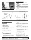
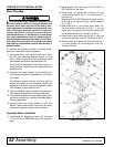
3-POINT UNITS
6. Attach floating upper mast (1) to shredder using
two hardened bushings, 1 x 5" hex bolts, lock nuts,
and four 3/4 x 3" spacers. See parts list for
hardware, page 48-48. (Keep hardware loose.)
CAUTION