


Owner Service 17
MAN0845 (1/12/2011)
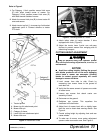
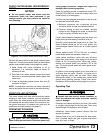
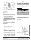
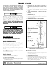
Figure 11. Belt Routing
BELT SERVICE
Belt Replacement
One of the major causes of belt failure is improper
installation. Before installing a new belt, check the fol-
lowing:
1. Check pulley shafts and bearings for wear.
2. Check pulley grooves for cleanliness.
3. Make sure spindles turn freely and without wobble.
If grooves require cleaning, moisten a cloth with a non-
flammable, non-toxic degreasing agent or commercial
detergent and water.
Avoid excessive force during installation. Do not use
tools to pry belt into pulley groove. Do not roll belt over
pulleys to install. This can cause hidden damage and
premature belt failure.
Belt Installation
1. Disconnect idler spring from deck lug I.
2. Slide belt under drive pulley A and over idler arm.
Position belt around drive pulley A.
3. Route belt around pulley B, idler C and pulley D as
shown.
4. Make sure belt is on drive pulley A, route around
idler E, and connect idler spring to lug I on deck.
5. Loosen bolt holding belt guide G and swing it away
from pulley F.
6. Grasp belt between spindle pulley F, spring loaded
idler E and spindle pulley D. Pull spring loaded
idler with belt to obtain enough belt length to route
it over pulley F. Make sure spring-loaded idler
pivots freely with belt installed.
NOTICE
■ Use care when installing or removing belt from
spring-loaded idler at step 6. Springs store energy
when extended and, if released suddenly, can
cause personal injury.
7. Adjust belt guide G to provide 1/8" to 3/16"
clearance from belt. Tighten bolt to 85 lbs-ft.
BLADE SERVICE
Before dismounting power unit or performing
any service or maintenance, follow these steps:
disengage power to equipment, lower the 3-point
hitch and all raised components to the ground,
operate valve levers to release any hydraulic pres-
sure, set parking brake, stop engine, remove key,
and unfasten seat belt.
Keep all persons away from operator control
area while performing adjustments, service, or
maintenance.
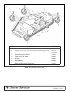
Blade Removal
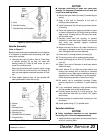
1. Remove Nylok bolt (5).
2. Remove blade lock (4) from groove in blade pin.
3. Remove blade (2) and pin (3) from spindle
assembly (1).
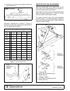
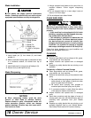
Figure 12. Blade Removal
1. Blade Spindle
2. Blade
3. Blade Pin
4. Blade Lock
5. 1/2NC x 3/4 Nylok
Bolt