


28 Assembly
MAN0260 (8/6/2004)
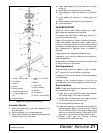
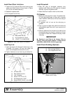
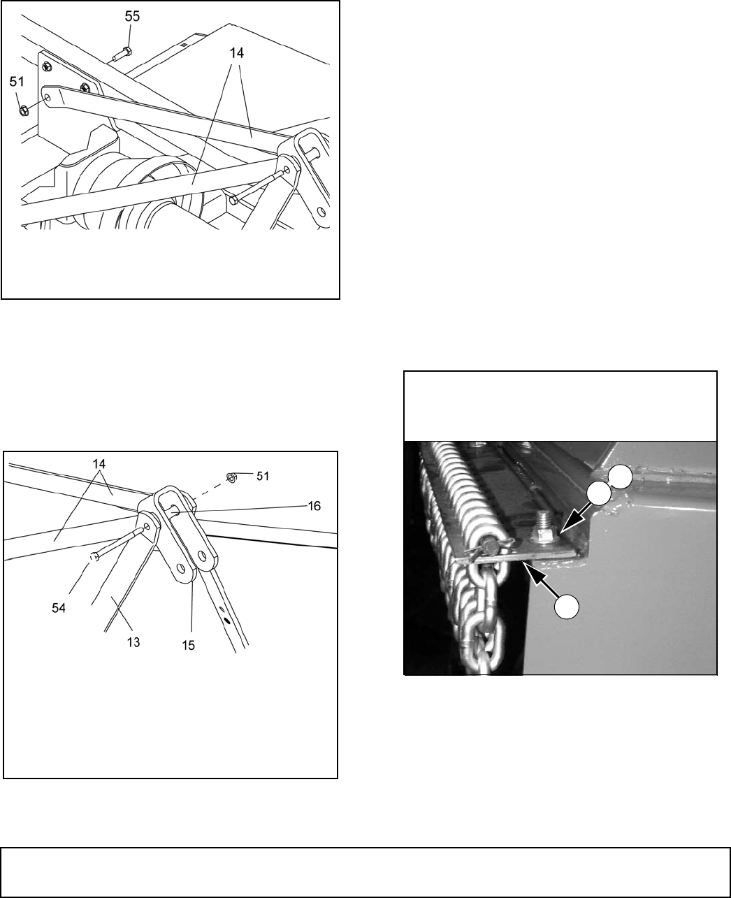
Install Rear Offset Link Arms
1. Loosen nut (51) and bolt (55) at rear frame lug and
attach rear offset link arm (14) as shown in Figure
24. (Do not use wheel tube bolt.)
2. Repeat for opposite side.
3. Do not tighten at this time.
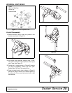
Figure 24. Right Rear Offset Link Installed
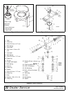
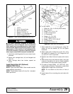
Install Top Link
1. Insert cap screw (54) through A-frame arms (13),
U-bracket (15), sleeve (16) and rear offset link
arms (14) and tighten securely with nut (51).
2. Tighten hardware on rear frame lug and offset link.
Figure 25. Top Link Assembled
Install Driveshaft
1. Slide QD yoke of driveshaft assembly onto
gearbox shaft. Make sure QD yoke pin is seated
securely in groove of gearbox shaft.
2. Attach shield anti-rotation chain to drive shield.
Fill Gearbox
1. Make sure vent plug hole is clear. Fill gearbox half-
full with high quality gear oil that has a viscosity
index of 80W or 90W and an API service rating of
GL-4 or GL-5.
2. Fill gearbox until oil runs out the side plug on
gearbox.
3. Pour in one pint of gear lube, wait five minutes and
add additional gear lube until it just comes out of
side hole.
4. Allow an additional five minutes for the lube to flow
through bearings, then check to make sure oil level
is at bottom of side hole. Replace side plug. Install
vent plug.
IMPORTANT
■ Gearbox is not filled at the factory. Prior to
delivery, make sure each gearbox is filled half-full
with 80W or 90W API GL-4 or GL-5 gear lube.
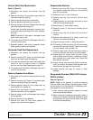
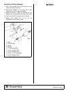
Install Chain Shielding (Optional)
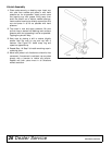
Figure 26. Chain Shielding Installed
(RD60 & RD72 Only)
14. Rear offset link arm
51. Nut, flanged lock 1/2 NC
55. 1/2 NC x 1-1/4 HHCS GR5
CD6497A-1
13. A-frame arms
14. Rear offset link arms
15. Link, U-bracket
16. Sleeve, .62 x .84 x 2.75
51. Nut,flanged lock 1/2 NC
54. Screw, HHCS 1/2 NC x 4-3/4 GR5
CM757
CD6497-2
15
3
14
CM768
3. Shield, chain plate
14. Bolt, carriage 3/8 NC x 1
15. Nut, flanged lock 3/8 NC
(Rev. 1/13/2006)