


24 Dealer Service
MAN0260 (8/6/2004)
RD60 & RD72
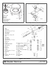
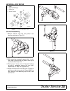
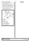
3. Install upper output bearing (13), shims (14), and
snap ring (15) on output shaft (12). Use new shims
equal to the thickness of the original shims.
4. Press output shaft assembly into housing from the
bottom opening.
5. Install spacer (16), lower output bearing (13),
shims (17), and snap ring (18) in bottom of
housing.
RDC54
3. Install shims (14), upper output bearing (8), spacer
(16), lower output bearing (8), shims (17), and
snap ring (15) on output shaft. Use new shims
equal to the thickness of the original shims.
4. Press output shaft assembly into housing from the
bottom opening.
5. Install snap ring (18) in bottom of housing.
All Models
6. Apply grease to lower seal lips (19), and press seal
over output shaft (5), using a round tube of the
correct diameter. Be sure not to damage the seal
lip. Press in housing so that the seal is recessed.
7. Insert protective washer (20) (RD60 & RD72 only)
by hand.
8. Install snap ring (21) and position it together with
seal (19) by pressing it into position. Verify that the
snap ring is seated properly.
9. Press bearing (8) into the housing, using a round
tube of the correct diameter and a hand press.
Secure with shims (9) and snap ring (10).
10. Install key (6) on input shaft (5).
11. Place gear (7) through top of housing and align the
two gears so they match.
12. While holding gear (7) in place, slide input shaft (5)
through the gear and bearing (8).
13. Slide spacer (29) (RDC54 only) and bearing (4)
over input shaft (5) and press into housing, using a
round tube of the correct diameter and a hand
press.
14. Slide shim (3) over input shaft and secure with
snap ring (2).
15. Check input shaft end float by moving the input
shaft by hand. If the end float is more than .012",
insert shim (9) between the rear bearing (8) and
snap ring (10).
16. Check that gear backlash is between .006" and
.016". You should not have to adjust the backlash.
17. Press in input seal (1), using a round tube of the
correct diameter. Be careful not to damage the seal
lip.
18. Press oil cap (11) on to the rear cover of housing,
using a round tube of the correct diameter.
19. Check the gearbox housing for leaks by plugging
all holes except one. Apply 4 psi compressed air
and immerse the gearbox in water to verify that
there are no leaks.
20. Remove the gearbox from water and dry off with
compressed air. Add SAE 80W or 90W EP oil until
it runs out of the side level hole. Tighten all plugs.
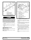
Install Gearbox
NOTE: Gearbox is heavy: do not attempt to move with-
out mechanical assistance.
1. Set gearbox on gearbox stand and fasten with
bolts and nuts. Torque bolts to 175 lbs-ft.
2. Attach drive sheave to output shaft. Secure using
castle nut and hardware previously removed.
3. Attach gearbox stand to mower using four hex
screws.
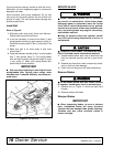
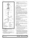
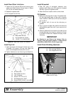
Install Drive Sheave
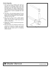
1. When gear stand is installed on mower, dimension
A (from the top of the mower deck to the center line
of the drive pulley) must be 2-1/16" (±1/32"). This is
a critical dimension and must be carefully adjusted
for proper belt life. Add or subtract shim washers
under idler pulley to align with drive pulley.
2. Tighten gear stand hardware.
3. Fill gearbox half full with SAE 90W gear lube.
4. Check level after waiting five minutes to permit
lube to work through bearings. Add lube, if
necessary, until gearbox is half full.
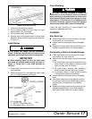
5. Replace driveline shield. Attach driveline to
gearbox.