


Dealer Service 27
MAN0475 (9/21/2005)
19. Check gearbox housing for leaks by plugging all
holes except one. Apply 4 psi compressed air and
immerse the gearbox in water to verify that there
are no leaks.
20. Remove gearbox from water and dry off with
compressed air. Add SAE 80W or 90W EP oil until
it runs out of side level hole. Tighten all plugs.
Gearbox Installation
NOTE: Gearbox is heavy: do not attempt to move with-
out mechanical assistance.
1. Set gearbox on gearbox stand and fasten with
bolts and nuts. Torque bolts to 175 lbs-ft.
2. Attach drive sheave to output shaft. Secure using
castle nut and hardware previously removed.
Torque castle nut to 170 lbs-ft.
3. Attach gearbox stand to mower using four flanged
1/2" lock nuts.
Drive Sheave Installation
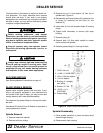
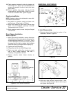
Refer to Figure 21.
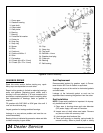
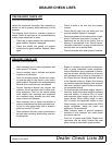
1. When gear stand is installed on mower, dimension
A (from the top of the mower deck to the center line
of the drive pulley) must be 2-7/16" (±1/32"). This is
a critical dimension and must be carefully adjusted
for proper belt life. Add or subtract shim washers
under idler pulley (3) to align with drive pulley (4).
2. Tighten gear stand hardware.
3. Fill gearbox half full with SAE 90W gear lube.
4. Check level after waiting five minutes to permit
lube to work through bearings. Add lube, if
necessary, until gearbox is half full.
5. Replace driveline shield. Attach driveline to
gearbox.
Figure 21. Drive Sheave Installation
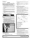
UNIVERSAL JOINT REPAIR
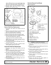
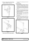
Figure 22. U-Joint Exploded View
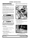
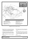
U-Joint Disassembly
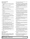
1. Remove external snap rings from yokes in four
locations as shown in Figure 23.
.
Figure 23
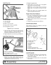
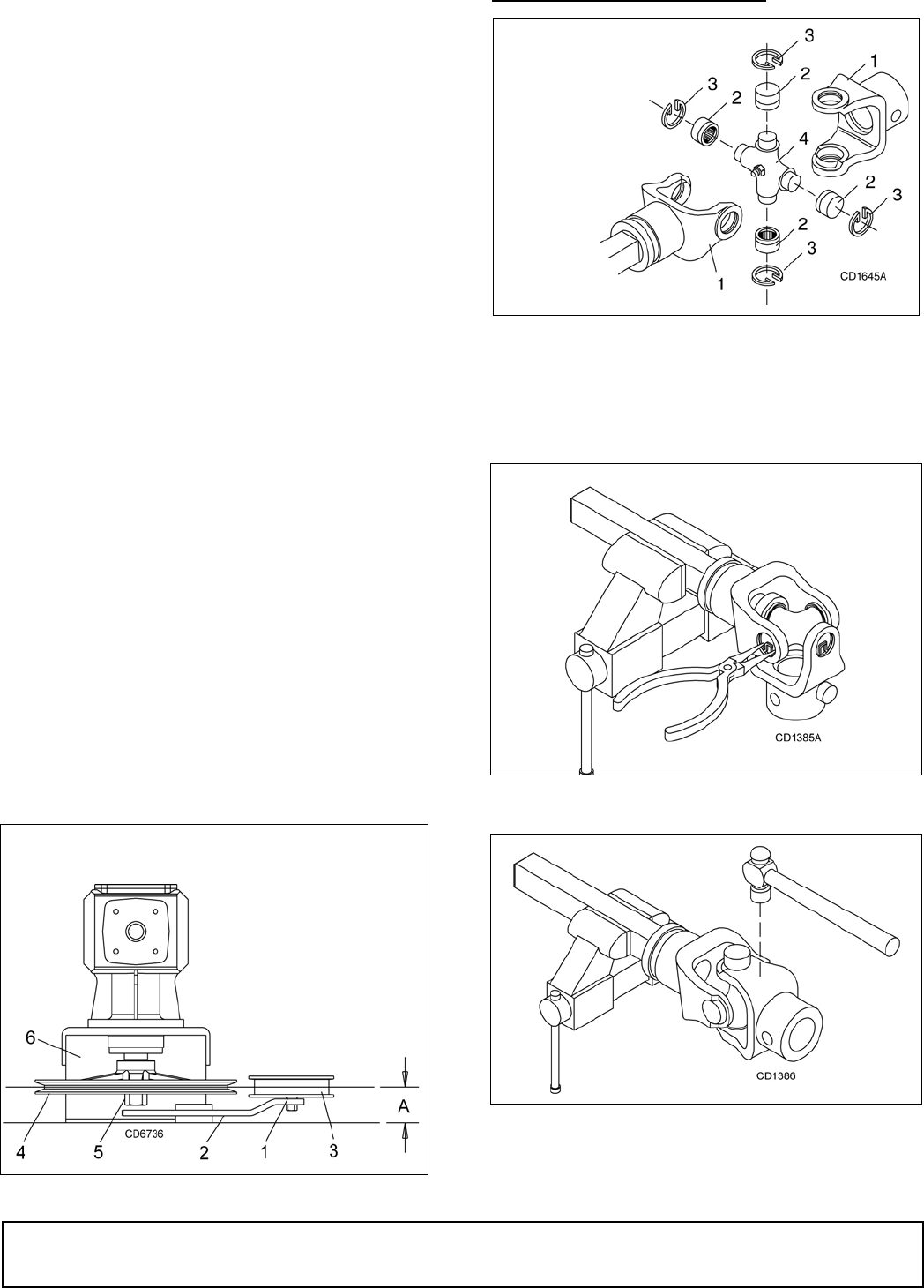
Figure 24
2. With snap rings removed, support drive in vise,
hold yoke in hand and tap on yoke to drive cup up
out of yoke. See Figure 24.
1. Shim
2. Idler arm
3. Idler pulley
4. Drive sheave
5. Castle nut & cotter pin
6. Gearbox stand
1. Yoke
2. Cup and bearings
3. Snap ring
4. Journal cross
(Rev. 11/25/2009)