


Installation 9
MAN0258 (Rev. 12/14/2007)
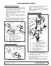
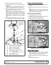
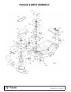
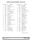
6. Install two cage nuts (63) into slots on deck.
7. Install three new 5/16 x 3/4 whiz bolts (33) into the
5/16 cage.
NOTE: The nylon flex coupler should move freely
up and down between the two flex coupler hubs.
8. Maintain alignment between the two flex coupler
hubs and tighten the three 5/16 whiz bolts.
NOTE: The four bolts holding the drive spindle on
the bearing mount have been left loose to help
align the two flex coupler hubs. The nylon flex
coupler should move freely up and down
approximately 1/16" between the two flex coupler
hubs.
9. Maintain alignment between the two flex coupler
hubs and tighten the four bolts to the drive spindle.
Figure 6. Vacuum Drive Mount Installation
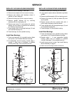
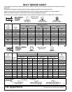
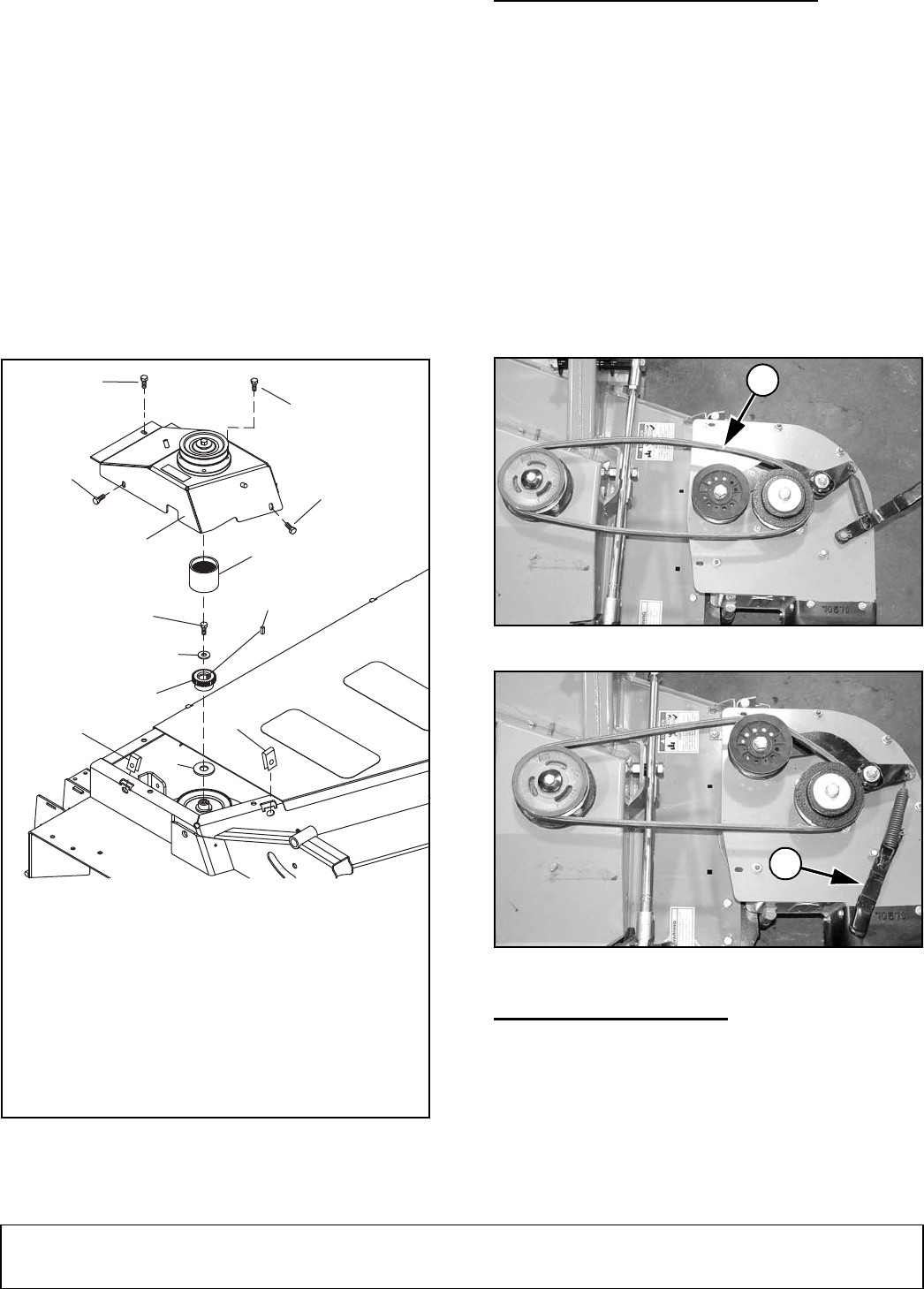
INSTALL VACUUM DRIVE BELT
1. Install belt (56) over sheaves and idler as shown in
Figure 7.
2. Engage belt tension lever (25) as shown in Figure
8.
NOTE: Check that belt is alignment and parts are
installed properly. Test run vacuum housing and
bearing mount for proper operation.
Remove Vacuum Drive Belt
1. Disengage belt tension lever (25).
2. Remove two 3-prong knobs (58) and vacuum drive
shield (57) from vacuum drive mount.
3. Remove belt (56) from sheaves and idler.
Figure 7. Vacuum Drive Belt Layout
Figure 8. Belt Tension lever Engaged
INSTALL BELT SHIELD
1. Place belt shield (31) over vacuum housing.
Secure using two whiz bolts (33), whiz nuts (34),
and one whiz bolt (32) as shown in Figure 9.
2. Install drive shield (57) and secure with two knobs
(58).
3. Engaged belt tension lever.
43
42
41
40
9
39
Loose Hardware
Tighten After
Installation (4)
33
CD6277-1
49
63
63
33
33
9. 70036 .406 x 1.27 x .120 Flat washer
33. 71851 5/16 NC x 3/4 Whiz bolt
39. 72656 Lower flex coupler
40. 480752 1/4 x 1/4 Square key
41. 78188 3/8 NF x 1 Cap screw GR5
42. 72658 Coupler sleeve
43. Vacuum drive mount (61" or 54")
49. 71495 Washer, 1" ID
63. 74047 5/16 NC Cage nut
56
25