Assembly 45
MAN0571 (Rev. 6/15/2007)
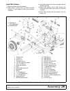
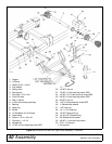
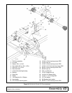
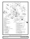
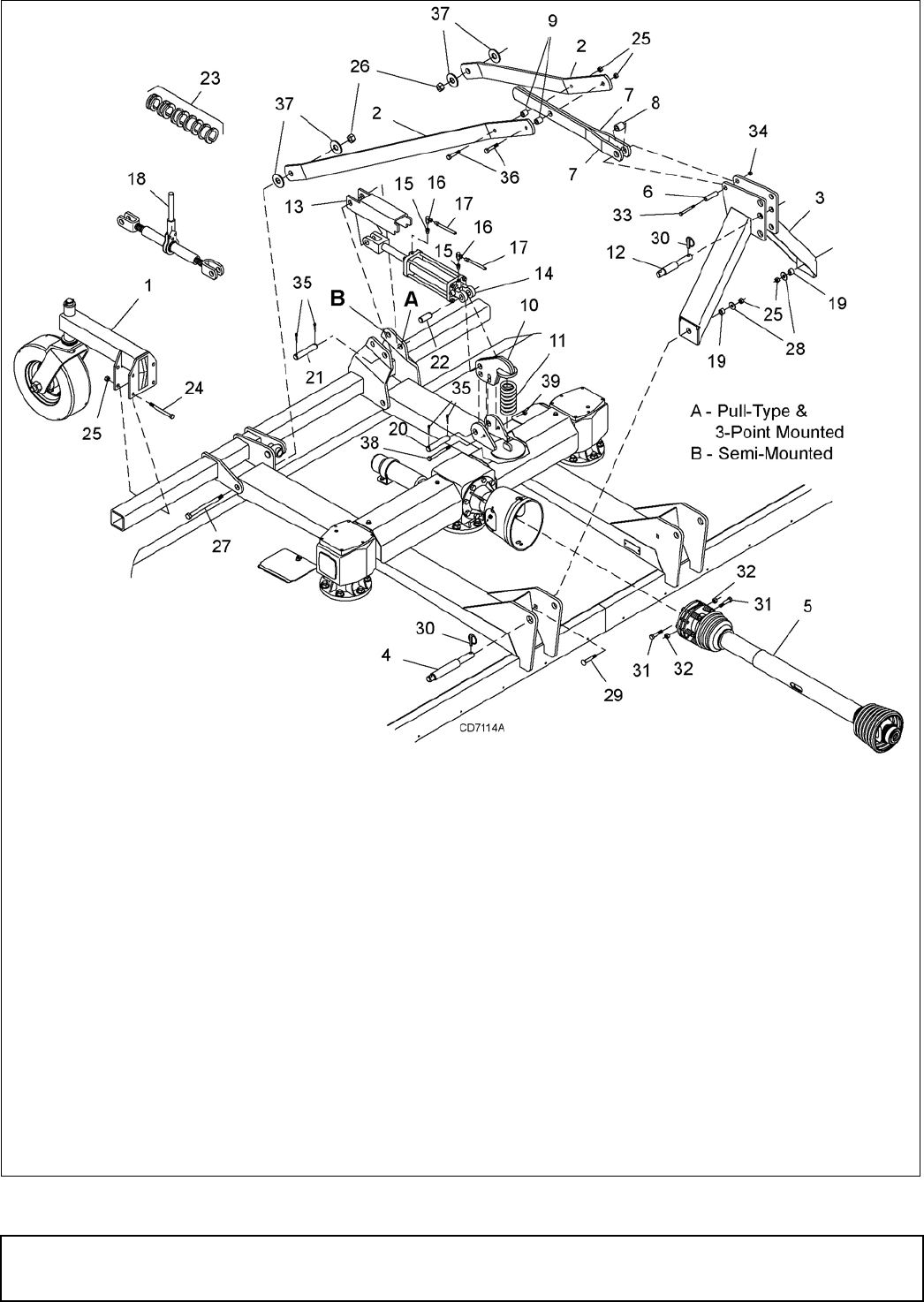
Figure 31. DS1260 & DS1440 Mounted Cutter Assembly
1. Tailwheel
2. Rear A-frame link
3. Front A-frame assembly
4. Lower hitch pin
5. Drive
6. Sleeve .781 x 1.38 x 2.40
7. Break link
8. Sleeve 1-3/8 x 1-3/4 x 1-1/4
9. Sleeve 5/8 x 1 x 1-1/4
10. Spring arm
11. Spring
12. Top link pin
13. Transport lock-up
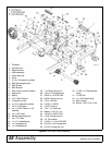
14. 3-1/2 x 8 Hydraulic cylinder
15. 1/2 to 1/4 Reducer
16. 1/4 x 1/4 90° Elbow with 1/16 restricter
17. 1/4 x 156" Hose
18. Ratchet adjustment link
19. Sleeve 5/8 x 1 x 13/16
20. 1 x 4-1/2 Headless pin
21. 1 x 5 Headless pin
22. 1 x 3 Headless pin
23. 1-1/4 Stroke control kit
24. 5/8 NC x 5 Hex head cap screw GR5
25. 5/8 NC Flange lock nut
26. 1 NC Lock nut
27. 1 NC x 12 Hex head cap screw GR5
28. 5/8 Standard flat washer
29. 5/8 NC x 2-1/2 Carriage bolt GR5
30. 7/16 x 2 Klik pin
31. 1/2 NC x 3 Hex head cap screw
32. 1/2 NC Lock nut
33. 3/4 NC x 4-1/2 Hex head cap screw GR5
34. 3/4 NC Lock nut
35. 1/4 x 1-1/2 Cotter pin
36. 5/8 NC x 3 Hex head cap screw GR5
37. 1" Standard flat washer
38. 1/2 NC x 5 Hex head cap screw GR5
39. 1/2 NC Flange lock nut


