32 Dealer Service
MAN0571 (Rev. 6/15/2007)
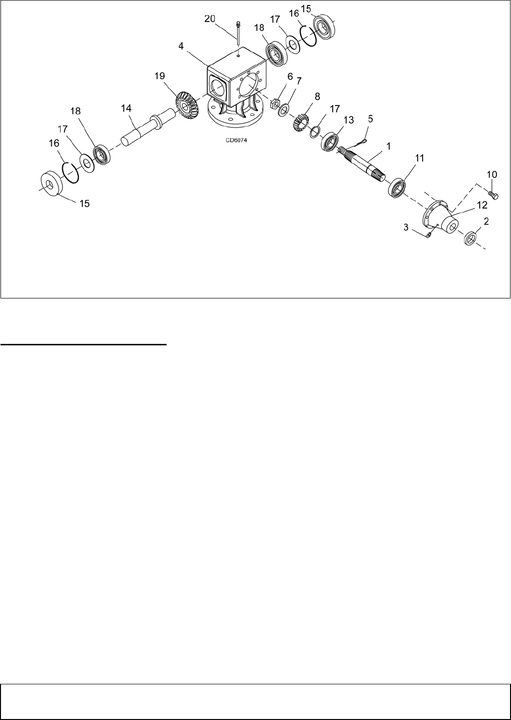
Figure 15. Splitter Gearbox Assembly
SPLITTER GEARBOX REPAIR (Figure 15)
NOTE: Replacing gears, shafts, bearings, and seals
may not be cost effective. Purchasing a complete
gearbox may be more economical.
Remove Gearbox from Cutter
1. Disconnect driveline from the tractor PTO and
remove it from center gearbox.
2. Remove dipstick plug (20) and siphon gear lube
from housing through this opening.
NOTE: Flex coupler driveline can not be removed
when center and side gearboxes are bolted in
place.
3. Disconnect and remove flex coupler driveline from
side of gearbox by:
a. Removing six 3/4 x 2-1/2 cap screws and 3/4 hex
nuts from around center gearbox
b. Removing tapered cap screw and hex nut from
flex coupler yoke
c. Rotating gearbox and slide flex coupler from
gearbox shaft.
Disassemble Gearbox (Figure 15)
1. Remove breather plug from top of gearbox.
2. Remove plug (3) from side of input housing (12)
and pour out gear oil.
3. Remove eight 10 mm cap screws (10) from around
input housing (12). Remove input shaft assembly
and housing.
4. Remove oil seals (15) (to be replaced) from both
sides of output shaft (14).
5. Remove snap rings (16) and shims (17) from both
sides of output shaft (14).
6. Support gearbox in a handpress and push on left
side of output shaft (14) to remove right bearing
(18) and gear (19) from housing.
7. Support housing in vise in a horizontal position.
8. Remove left bearing (18) by using a punch and
hammer from right side of housing. Drive bearing
out of housing.
9. Remove cotter pin (5), castle nut (6), shim (7), gear
(8) and shim (17) from input shaft (1).
10. Remove seal (2) (to be replaced) from input
housing (12).
11. Support input housing in a vise and remove
bearing (11) by using a punch and hammer. Drive
bearing out of housing.
12. Inspect gears for broken teeth and wear. Some
wear is normal and will show on loaded side.
Forged gear surfaces are rough when new. Check
that wear pattern is smooth.
1. Input shaft
2. Oil seal, metric 50 x 90 x 10
3. Oil plug, 3/8
4. Gearbox housing
5. Cotter pin
6. Castle nut M40 x 1.5
7. Spacer
8. Gear 16T M8 (540 rpm)
8. Gear 22T M8 (1000 rpm)
10 Cap screw, M10 x 25
11. Bearing, cup & cone
12. Housing, Gearbox Input
13. Bearing, cup & cone
14. Output shaft
15. Oil seal, metric 45 x 85 x 10
16. Snap ring, 85 dia.
17. Shim
18. Bearing, cup & cone
19. Gear 16T M8 (1000 rpm)
19. Gear 22T M8 (540 rpm)
20. Dipstick plug
