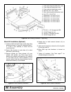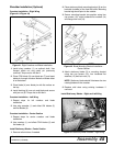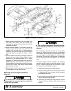
Assembly 47
MAN0764 (11/5/2008)
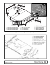
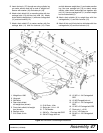
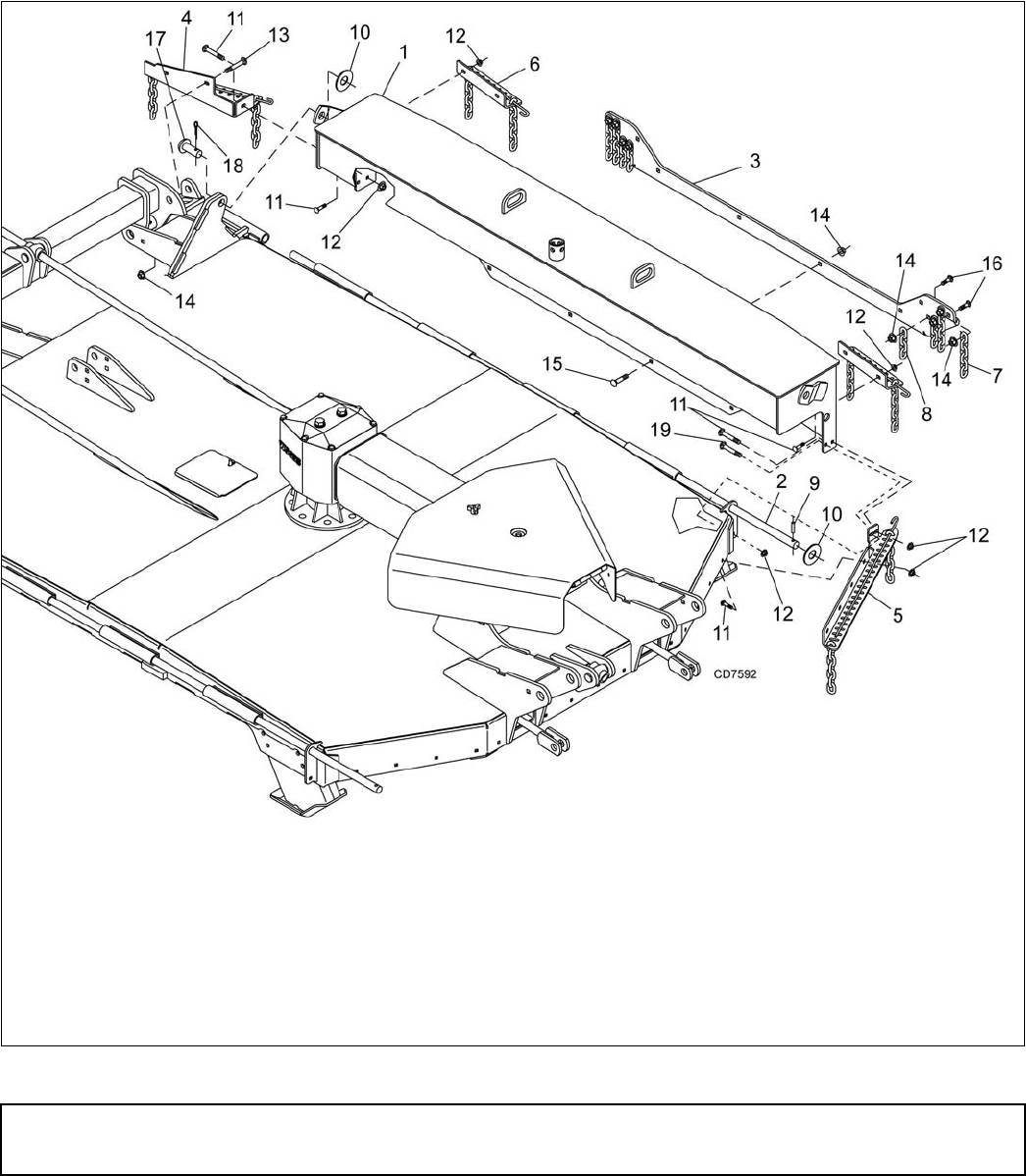
5. Insert clevis pin (17) through rear wing cylinder lug
on center section and lug on end of weight box.
Secure with washer (10) and cotter pin (18).
6. Attach chain shield (4) to mounting plate with two
carriage bolts (13) and two lock nuts (14). Attach
chain shield to weight box (1) with one carriage bolt
(11) and one locknut (12).
7. Attach chain shield (5) to center section with five
carriage bolts (11) and five locknuts (12). Place
end tab between weight box (1) and center section
lug. Use one carriage bolt (19) to attach center
section, chain shield, and weight box together with
nut (12). Use one carriage bolt (11) to attach weight
box to chain shield (5).
8. Attach chain shields (6) to weight box with four
carriage bolts (11) and four locknuts (12).
9. Attach 6-link and 4-link chain to skid shoe with four
carriage bolts (16) and four locknuts (14).
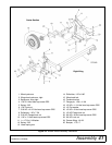
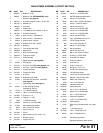
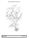
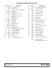
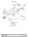
Figure 45. BW1620X Counterweight Installation
1. Weight box 1300
2. Hinge pin
3. Skid shoe
4. Rear chain shield,
left weight box (shown)
5. Front chain shield, left weight
box (shown)
6. Bracket, chain
7. 5/16 Chain, 6-link
8. 5/16 Chain, 4-link
9. Spring pin, 1/4 x 1-1/2
10. 1" Flat washer
11. 3/8 NC x 1 Carriage bolt GR5
12. 3/8 NC Flange lock nut
13. 1/2 NC x 1-1/4 Carriage bolt
GR5
14. 1/2 NC Flanged lock nut
15. 1/2 NC x 1-1/2 Carriage bolt
GR5
16. 1/2 NC x 2 Carriage bolt GR5
17. Clevis pin, 1 x 2.26
18. 1/4 x 1-1/2 Cotter pin
19. 3/8 NC x 1-1/2 Carriage bolt
GR5


