Parts 49
MAN0810 (9/24/2009)
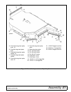
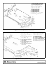
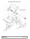
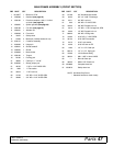
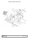
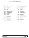
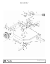
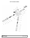
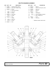
MAIN FRAME ASSEMBLY (REAR SECTION)
REF PART QTY DESCRIPTION
6 1003491 1 Attitude rod
11 1003495 2 Hinge pin
17 1032200 1 Center wheel yoke
18 57050 1 Access hole cover
19 1032225 1 Spring arm
20 13316 1 Spring
21 29547 1 Hydraulic cylinder 3 x 8 (see page 64)
22 1004814 1 Transport lock-up
23 24098 1 1-1/4 Cylinder stroke control kit
24 23650 1 Ratchet adjustable link bun-
dle(optional)
25 1017143 1 SMV Mounting link
26 62484 1 SMV Socket
27 1004251 1 SMV Bracket
28 24611 1 SMV Emblem
29 ----- 2 Tire & hub (see page 59)
30 1003690 2 Adjustable link
32 1631 1 1 x 2.72 Headless pin
33 8345 1 1 x 4.08 Headless pin
34 8346 1 1 x 4.58 Headless pin
38 65130 2 Spacer, 1"
39 27267 1 Pipe, 1" Schedule 40 x 3.75"
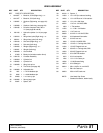
REF PART QTY DESCRIPTION
40 11893 1 1/2 x 1/4 Pipe reducer bushing
41 10290 1 1/4 x 1/4 Elbow w/ 1/16 restricter
42 8669 1 1/4 x 1/4 x 156 Hose
50 1003606 * 1 NC x 6 HHCS GR5
51 46752 1 NC x 4-1/2 HHCS GR5
52 1863 * 1" Flat washer
54 3132 * 1 NC Hex nut
55 34279 * 1 NC Lock nut
64 3489 * 1/2 NC x 3 HHCS GR5
65 3508 1/2 NC x 4-1/2 HHCS GR5
66 14406 * 1/2 NC x 1 Carriage bolt, GR5
68 11900 * 1/2 NC Flanged lock nut
70 14350 * 3/8 NC Flanged lock nut
73 16148 5/16 NC x 3/4 Carriage bolt
77 14139 * 5/16 NC Flanged lock nut
78 1282 * 1/4 NC x 1/2 Round head screw
79 5288 * 1/4 NC Hex nut
80 1285 * 1/4 x 1-1/2 Cotter pin
81 66016 * 1/4 x 1-1/2 Spring pin
82 12296 * 1/4-28 Grease fitting
HHCS Hex Head Cap Screw
* Standard hardware, obtain locally


