14 Operation
MAN0632 (5/15/2007)
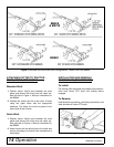
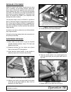
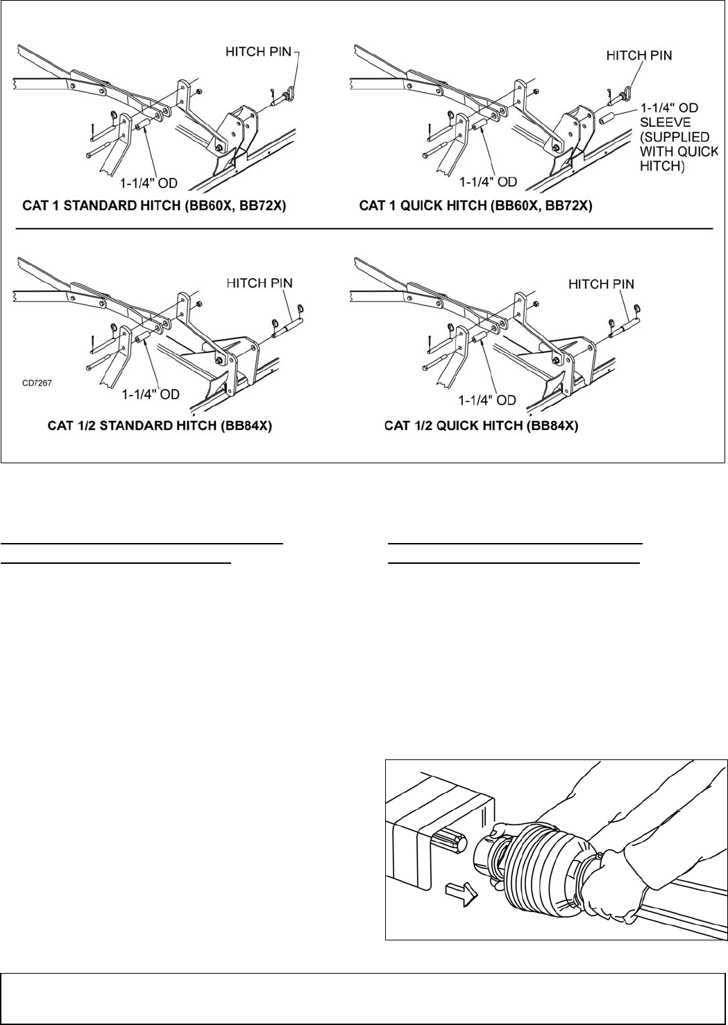
Figure 4. Standard Hitch and Quick Hitch Configurations - BB60X, BB72X & BB84X
ATTACHING CUTTER TO TRACTOR -
BB60X, BB72X, BB84X ONLY
Standard Hitch
1. Position tractor 3-point arms between the mast
plates and secure with hitch pins and cotter pin.
See left side of Figure 4. Note pin orientation for
the BB84X.
2. Connect the tractor top link to the cutter A-frame
using the upper holes and the appropriate
hardware. The break link must be placed in the
lower holes of the A-frame.
Quick Hitch
1. Position tractor 3-point arms between the mast
plates and secure with hitch pins and cotter pin.
See right side of Figure 4. Note pin orientation for
the BB84X.
2. Attach tractor with the quick hitch to the cutter and
secure according to the quick hitch manufacturer's
instructions.
INSTALLATION AND REMOVAL
OF DRIVELINE (TRACTOR PTO)
To Install:
Pull locking collar back and at the same time push driv-
eline onto tractor PTO shaft until locking device
engages.
To Remove:
Hold driveline into position, pull locking collar back, and
slide driveline off tractor PTO shaft.
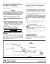
Figure 5. Lock Collar
BB60X
& BB72X
BB84X


