Assembly 11
29927 (Rev. 3/14/2008)
ASSEMBLY
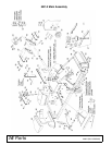
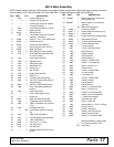
Side Shield (See page 16)
Attach side shields (39 & 48) to mower with 3/8 x 1"
bolts and lock nuts. A side discharge chute (48) may be
installed on right end of mower in place of side shield
(30).
Center Belt Shield Bracket & Pivot Pipe
(See page 16)
Attach rear pivot pipe (17) and center belt shield
bracket (10) to mower using 3/8 x 1-1/4 bolt, nut, and
lock washer. Remove rear bolt from bracket (47).
Secure center of pipe (17) and bracket (47) with 3/8 U-
bolt (67), nut and lock washer.
Center Belt Shield (See page 16)
Attach center belt shield (9) to bolts welded in mower
and belt shield bracket (10) using 3/8 nuts and lock
washers.
Side Skids (See page 16)
Bolt skids in such a position that they will be carried
close to the ground, but not ride continuously on the
ground when mower is operated at desired mowing
height. Use 3/8 x 1" heat treated bolts (torqued to 35
lbs-ft), lock washers, and nuts.
Front Toe Guards (See page 16)
Front toe guards (49) are furnished for some mowers.
When provided, bolt them to front of mower using 3/8
NC x 3/4" carriage bolts and 3/8" flange lock nuts.
Idler Frame (See page 16)
Assemble idler sheaves to inside of adjustment slots as
shown using 5/8 x 3-1/2 carriage bolts, flat washers,
lock washers and nuts. Move tractor drawbar adjust-
ment to bottom adjustment hole on the tractor.
Slide idler channel frame assembly (20) between the
drawbar and the drawbar plate attachment bolts of the
tractor. Attach with the clamp plates that are furnished
using 1/2 x 2" bolts, lock washers and nuts.
Attachment Arms (See page 16)
Bolt attachment arms (18) to tractor with three 5/8 x
1-1/4 bolts and lock washers in each.
PTO Sheave (See page 16)
Remove paint from bore of sheave (32). Put 1" splined
tapered bushing (31) in sheave (32), and insert screws
to hold bushing in place, but do not tighten.
Mounting Mower (See page 16)
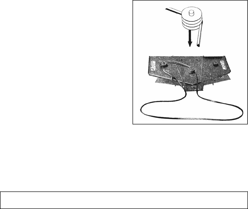
Slide mower under tractor. At this point, the belt must
be looped over the pivot pipe. Screw guide rod (22) into
rear of pipe (17). Do not tighten. Insert guide rod into
second hole from bottom of idler bracket plate (for
average mowing conditions).
Attach two adjustment arms (16) with single hole end to
mower, other end to bottom of attachment arms using
5/8 x 1-1/2 clevis pins, washers, and safety pins. Place
rear clevis pin in the most forward adjustment hole
from rear of initial setting. This may need to be
changed after belt is installed and lined up.
Belt Assembly and Adjustment
Position and pin push arms to the mounting brackets
using 5/8 x 1-1/2 clevis pin and safety pins.
First put belt on the bottom groove, right hand side of
the center sheave. Then thread it to the left, around the
left hand sheave.
Figure 4.
Bring the belt back across the center sheave in the
center groove over to the right outside sheave.


