


8 PN-53661 (Rev. 12/96)
Hydraulic Hose Installation Instructions
WARNING
J Keep hands and body away from pres-
surized lines. Use paper or cardboard, not
body parts to check for leaks. Wear safety
goggles. Hydraulic fluid (oil) under pres-
sure will easily penetrate skin and can
cause serious injury or death.
J Make sure that all operating and
service personnel know that in the event
hydraulic fluid penetrates skin, it must be
surgically removed within a few hours by
a doctor familiar with this form of injury, or
gangrene, serious injury or death can
result. CONTACT A PHYSICIAN IMMEDI-
ATELY IF FLUID ENTERS SKIN OR EYES.
J Make sure all hydraulic hoses, fittings
and valves are in good condition and not
leaking before starting powerunit orusing
equipment. Check and route hoses care-
fully to prevent damage. Hoses must not
be twisted, bent sharply, kinked, frayed,
pinched, or come into contact with any
moving parts. Operate moveable compo-
nents through full operational range to
check clearances. Replace any damaged
hoses immediately.
J Air in hydraulic systems can cause
erratic operation and allows loads or
equipment components to drop unexpect-
edly. Before operating or allowing anyone
to approach the equipment, purge any air
in the system by operating all hydraulic
functions several times after connecting
equipment, connecting hoses, or doing
any hydraulic maintenance.
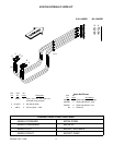
Refer to page 11. A hose kit is available that will
attach the loader feed lines directly into the rear
tractor hydraulic ports. Prepare each hose assembly
(1) by attaching a 90° swivel (2) and male quick-
disconnect (3) onto the end of hose (without protector
sleeve). Attach the opposite end of the hydraulic hose
(with protector sleeve) into the loader feed lines.
Refer to illustration on page 10 for the proper orienta-
tion of the hoses.
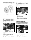
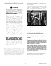
Connect the end of the hose with the quick disconnect
coupler into the female couplers on the rear of the
tractor to complete the circuit, as shown in Figure 7.
D C AB
Figure 7. Hose Connection to Tractor
Once all hoses are connected, start the tractor and
run the loader valve lever to check for leaks and purge
any remaining air from the hydraulic system.
Check to be sure the valve handle directions
correspond with the motion of the loader. See chart
on page 11.
Once all hose routings are verified, identify each
circuit by placing a matching colored band around the
male and female quick disconnect couplers. The color
coded bands will make re-installation easier when the
loader is removed from the tractor.
Attach the plastic tie straps (included in kit) around
the hoses to keep them tightly bundled and away from
contact with the ground or other moving parts on the
tractor or loader. Be sure that adequate slack is left in
the hoses so they can move as the loader moves
through it’s full range of motion.
Refer to either the 195 or 215 Loader Operator’ s
Manual to complete the loader installation.