


6
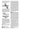
Computed kickback angle (CKA) Ta ble
BAR
P/N Length
CHAIN P/N
20”
MODEL
380 21
_
CKA without
chain brake
952044795 952051482
330
21
_
952044795 20”
952051482
23
_
952051483530044833330 22”
NOTE
:
This saw complies with F ederal
OSHA regulations for commercial logging.
SAFETY NOTICE:
Exposure to
vibrations through prolonged use of gasoline
powered hand tools could cause blood
vessel or nerve damage in the fingers,
hands, and joints of people prone to
circulation disorders or abnormal swellings.
Prolonged use in cold weather has been
linked to blood vessel damage in otherwise
healthy people. If symptoms occur such as
numbness, pain, loss of strength, change in
skin color or texture, or loss of feeling in the
fingers, hands, or joints, discontinue the use
of this tool and seek medical attention. An
anti-vibration systemdoes not guarantee the
avoidance of these p roblems. Users who
operate power tools on a continual and
regular basis must monitor closely their
physical condition and the condition of this
tool.
SPECIALNOTICE:
Your sawisequipped
with a temperature limiting muffler and spark
arresting screen which meets the
requirements of California Codes 4442 and
4443. All
U.S.
forest land and the states of
California, Idaho, Maine, Minnesota, New
Jersey, Oregon, and Washington require
many internal combustion engines to be
equipped with a spark arrestor screen by
law. If you operate a chain saw in a state or
locale where such regulations exist, you are
legally responsible for maintaining the
operating condition of these parts. Failure to
do so is a violation of the law . Refer to the
SERVICE section for maintenance of the
Spark Arrestor.
Failure tofollowall Safety Rules andPrecau-
tions can result in serious injury. If situations
occur which are not covered in this manual,
use care and good judgement. If you need
assistance, contact your Authorized Service
Dealer.
ASSEMBLY
Protective gloves (not provided) should be
worn during assembly.
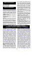
ATTACHING THEBAR&CHAIN
(If not
already attached)
WARNING:
If received assembled,
repeat allsteps toensure yoursaw isproper-
ly assembled and all fasteners are secure.
Always wear gloves when handling the
chain. The chain is sharp and can cut you
even when it is not moving!
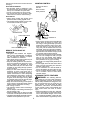
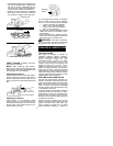
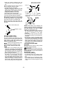
S
Loosen and remove the chain brake nuts
and the chain brake from the saw.
S
Remove the plastic s hipping spacer (if
present).
Chain Brake
Chain Brake Nuts
Assembly
Tool
Shipping
Spacer
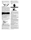
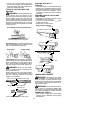
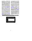
S
An adjusting pin and screw is used to ad-
just the tension of the chain. It is very im-
portant when assembling the bar, that the
pin located on the adjusting screw aligns
into a hole inthe bar.Turning the screwwill
move the adjustment pin up and down the
screw. Locate this adjustment before you
begin mounting the bar onto the saw . See
illustration below.
Adjustment
Screw
S
Turn the adjusting screw counterclock-
wise to move the adjusting pin almost as
far asit willgo tothe rear.This should allow
the pin to be near the correct position. Fur-
ther adjustment may be necessary as you
mount the bar.
S
Mount the bar as illustrated.
S
Slide the bar toward the rear of the saw as
far as possible.
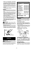
S
Prepare the chain by checking the proper
direction. Without following the illustration
it is easy to place the chain on the saw the
wrong direction. Use the illustration of the
chain to determine the proper direction.
S
Place the chain onto the sprocket located
behind the clutch drum (see illustration).
Fit the chain between the teeth in the
sprocket.
S
Start at the top of the bar and fit chain into
groove around the guide bar.
S
After chain is installed, pull bar forward un-
til chain is snug in the groove of the bar.