


17
ADJUSTING BRAKE FORCE
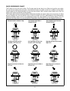
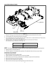
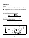
Figure 14
1. Place the Z-series on level surface without the brake engaged and place blocks behind the wheels.
2. Turn the engine OFF and remove the key from the ignition.
3. From underneath the Z-series directly behind the caster wheel pivot bar, locate the brake rods. There are two,
one on the right and one on the left. (See Figure 14)
4. The factory sets a 1/16” gap minimum between the brake arm and frame of the Z-Series.
More adjustment may be necessary. (See Figure 14)
NOTE: If after adjusting the brake, the proper force has not been obtained more adjustment may be required.
5. Repeat process on the other brake rod.
6. Check the operation of the brakes before operating. If the adjustment does not help, see your dealer.
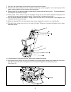
STEERING ADJUSTMENT
1. Remove the ignition key from ignition switch.
2. Detach the bottom of the rubber boot cover on the driver handles.
3. Slide the boot cover all the way up (toward the drive handles) to access the drive handle bolts.
4. Remove both bolts securing the drive handles.
5. Remove the drive handles and the rubber boot.
6. Remove the four bolts securing the retaining plate to the control tower cover.
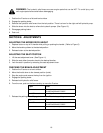
If: Then:
Increased force is needed Rotate brake rods clockwise.
Decreased force is needed Rotate brake rods counterclockwise.
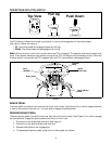
Brake Rod
Frame
Brake Arm
Measure Gap