


18
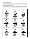
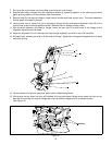
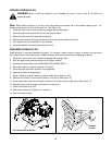
7. Pull up on the control tower cover and slide up and over the control tower.
8. Remove both safety switches from their respective holders by squeezing together on the retaining clips while
gently pushing upward until the switches clear the brackets.
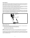
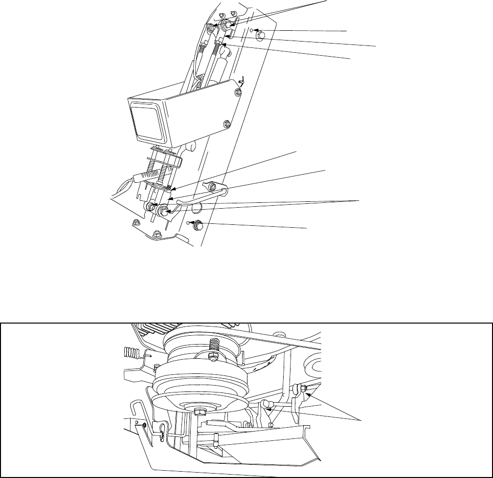
9. Remove bolts (A) that secure linkage to upper control handles and lower control arms. The shock absorbers
should remain connected to linkage.
10. Insert quarter inch by seven inch pin or equivalent through the top and bottom alignment holes (B) of the
control arms to secure arms at positive neutral. (Remove floor for access to lower holes.)
11. With the shock absorber still bolted to linkage, loosen the jam nuts (C) at both ends of the linkage so the
alignaball adjustment can be made.
12. Adjust the alignaball (D) until retaining bolts slips through alignaball, and hole in arm, with little effort.
13. Re-install bolts, washers and nuts in all four ends of linkage. Tighten jam nuts against alignaball ends to keep
ends from turning.
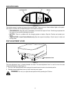
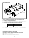
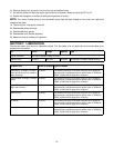
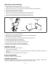
14. Lift rear wheels off of ground using floor jack or other suitable lifting device.
15. With quarter inch by seven inch pins still installed in the top and bottom linkage arms, loosen the jam nuts at
both the front and rear (A) ends of linkage that runs from bottom linkage arms to hydrostatic pumps.
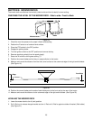
(See Figure 15)
Figure 15
A
A
B
B
C
D
D
C
Jam Nuts