


5
Section 2: Assembly
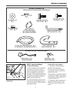
Contents of Hardware Bag
(Parts are shown at actual size unless noted otherwise)
Flat Washer, 5/16"
Qty: 4
Cotter Pin, 3/32" x 5/8"
Qty: 6
Hex Flange Lock Screw,
5/16"-18 x 3/4" Qty: 2
Shift Link - Gear Select Lever
(shown reduced size) Qty: 1
Hex Flange Lock Screw,
1/4"-20 x 1/2" Qty: 2
Hex Flange Lock Nut,
1/4-20" Qty: 2
Plastic Cable Tie
(shown reduced size)
Qty: 1 (Recoil Start Model)
Qty: 3 (Electric Start Model)
Oil Drain Tube (shown reduced size) Qty. 1
( for changing oil - see Maintenance Section )
Shift Rod Mounting Plate
(shown reduced size) Qty: 1
Battery Charger Qty: 1
(shown reduced size)
Ignition Keys Qty: 2
(shown reduced size)
(Parts shown below are for electric start model)
STEP 3: Electric Start Model
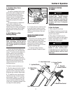
A. Secure Wire Harness
1.
At the unattached end of the electrical
wire harness, there are four wires at-
tached to a large plastic connector and
two wires attached to a small plastic
connector. Plug the large connector into
the bottom of the ignition keyswitch that
is located on the underside of the han-
dlebar console (not pictured).
2. Use two cable ties to secure the wire
harness to the right handlebar and away
from any moving parts. Place the ties an
equal distance apart.
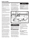
B. Attach Wire Leads to Battery
1. The battery is located at the rear,
right-side of the engine deck.
2. At the lower end of the electrical
wiring harness, locate a red wire lead
and a black wire lead.
• Plug terminal on red (positive) wire into
red terminal (U, Figure 2-3) on battery.
• Plug terminal on black (negative) wire
into black terminal (V).
3. If applicable, attach wire harness to
engine deck using J-clips (W, Figure
2-4) as shown. Bend J-clips over to
secure.
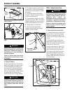
A
D
E
D
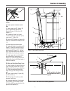
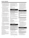
Figure 2-2: Attach handlebars and struts
to engine deck.