


6
Figure 4
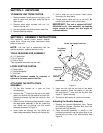
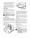
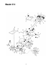
3. Lift up the handle assembly and align the bottom
holes in the handle assembly with the holes in
the pivot bracket. Insert hex bolt (with Hex nut
retainer attached through the round hole). The
head of hex bolt and retainer bracket should be
to the right hand side of the unit. See Figure 5.
Figure 5
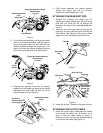
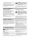
4. Place the hex opening of the hex nut retainer
bracket over the flange nut securing the handle
adjustment lock and install the lock nut on the
lower shoulder bolt. See Figure 6.
Figure 6
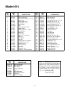
5. Pivot handle assembly into position desired.
Tighten the bottom bolt and nut securely.
Tighten the handle adjustment lock.
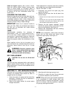
ATTACHING THE GEAR SHIFT ROD
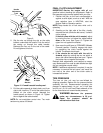
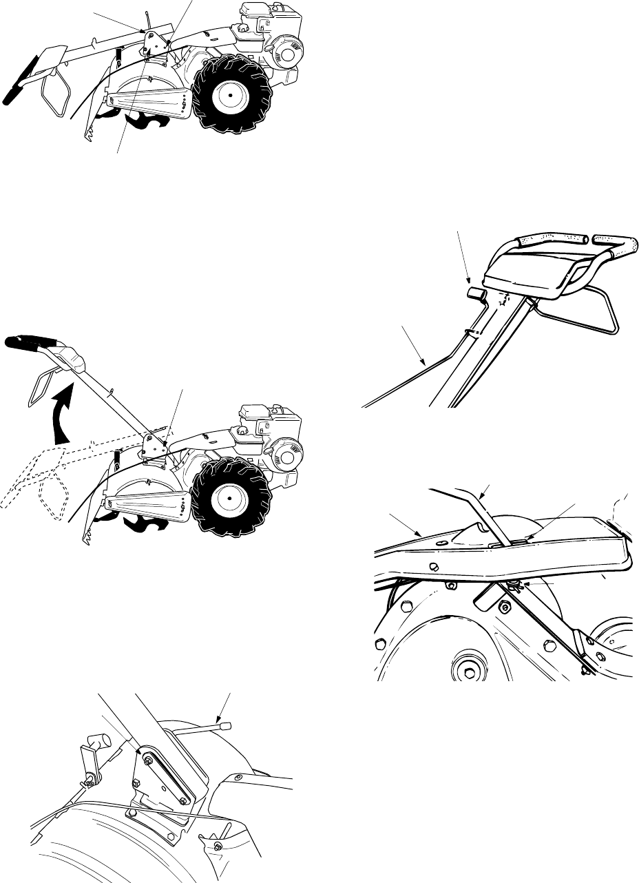
1. Remove the T-handle, nut, hairpin clip, flat
washer and rubber washer from the end of the
gear shift rod. Slide the rod up through the
bracket on the front of the handle assembly. See
Figure 7.
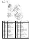
2. Insert the end of the gear shift rod through the
opening in the top of the shift cover, and into the
shift bracket. See Figure 8. Secure with rubber
washer first, then flat washer and hairpin clip.
Figure 7
Figure 8
3. Install the nut and T-handle on the gear shift rod.
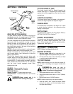
ATTACHING THE CLUTCH CABLE
1. Route the clutch cable underneath the handle
and through the cable clip. Be careful not to
bend or kink the cable. Refer to Figure 9.
Remove one hex nut from the threaded casing
on the end of the cable. See Figure 10.
Pivot Bracket
Handle Adjustment
Lock
Flange Nut
Flange Nut Retainer Bracket
Shoulder Bolt
Lock Nut
Lift up
Handle
Flange Nut Retainer Bracket
Shoulder Bolt
Lock Nut
Hex Hole in
Retainer Bracket
over Flange Nut
Handle Adjustment
Lock
T-Handle
Gear Shift
Rod
Shift Cover
Gear Shift Rod
Opening
Rubber Washer
Flat Washer
Hairpin Clip