Table of Contents
viii
List of Figures
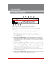
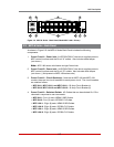
2.1. MPC-H Series - Front Panel (Model MPC-16H Shown) . . . . . . . . . . . . . . . . . . . . . . . . . . . 2-1
2.2. MPC-H Series - Back Panel (Model MPC-16H-1 Shown) . . . . . . . . . . . . . . . . . . . . . . . . . .
2-3
2.3. MPC-20V Series - Hardware Description (Model MPC-20VD20-1 Shown) . . . . . . . . . . . . 2-5
5.1. The Plug Status Screen (Text Interface; MPC-20V Shown)
. . . . . . . . . . . . . . . . . . . . . . . . 5-2
5.2. The Home Screen (Web Browser Interface) . . . . . . . . . . . . . . . . . . . . . . . . . . . . . . . . . . . .
5-3
5.3. The System Parameters Menu (Text Interface) . . . . . . . . . . . . . . . . . . . . . . . . . . . . . . . . . .
5-6
5.4. The System Parameters Menu (Web Browser Interface) . . . . . . . . . . . . . . . . . . . . . . . . . .
5-6
5.5. The Add User Menu (Text Interface) . . . . . . . . . . . . . . . . . . . . . . . . . . . . . . . . . . . . . . . . .
5-23
5.6. The Add User Menu (Web Browser Interface)
. . . . . . . . . . . . . . . . . . . . . . . . . . . . . . . . . 5-23
5.7. The Add Plug to Group Menu (Text Interface)
. . . . . . . . . . . . . . . . . . . . . . . . . . . . . . . . . 5-31
5.8. The Add Plug Groups Menu (Web Browser Interface) . . . . . . . . . . . . . . . . . . . . . . . . . . .
5-31
5.9. The Plug Parameters Menu (Text Interface)
. . . . . . . . . . . . . . . . . . . . . . . . . . . . . . . . . . . 5-35
5.10. The Plug Parameters Menu (Web Browser Interface)
. . . . . . . . . . . . . . . . . . . . . . . . . . . 5-35
5.11. Boot Priority Example 1 . . . . . . . . . . . . . . . . . . . . . . . . . . . . . . . . . . . . . . . . . . . . . . . . . . . 5-38
5.12. Boot Priority Example 2 . . . . . . . . . . . . . . . . . . . . . . . . . . . . . . . . . . . . . . . . . . . . . . . . . . . 5-39
5.13. Serial Port Configuration Menu (Text Interface)
. . . . . . . . . . . . . . . . . . . . . . . . . . . . . . . . 5-40
5.14. Port Configuration Menu (Web Browser Interface) . . . . . . . . . . . . . . . . . . . . . . . . . . . . . .
5-40
5.15. Remote/AUX Port Configuration Menu (Text Interface)
. . . . . . . . . . . . . . . . . . . . . . . . . . 5-44
5.16. Remote/AUX Port Configuration Menu (Web Browser Interface) . . . . . . . . . . . . . . . . . . .
5-44
5.17. Network Parameters Menu (Text Interface) . . . . . . . . . . . . . . . . . . . . . . . . . . . . . . . . . . . .
5-47
5.18. Network Configuration Menu (Web Browser Interface)
. . . . . . . . . . . . . . . . . . . . . . . . . . 5-47
9.1. The Help Menu (Administrator Mode; Text Interface) . . . . . . . . . . . . . . . . . . . . . . . . . . . . . 9-4
11.1. The Test Menu (Text Interface, Administrator Mode Only) . . . . . . . . . . . . . . . . . . . . . . . .
11-2
14.1. Web Access Parameters (Text Interface Only) . . . . . . . . . . . . . . . . . . . . . . . . . . . . . . . . . 14-1
B.1. RS232 Console Port Interface
. . . . . . . . . . . . . . . . . . . . . . . . . . . . . . . . . . . . . . . . . . . . Apx-2
B.2. MPC Series AUX Port Interface . . . . . . . . . . . . . . . . . . . . . . . . . . . . . . . . . . . . . . . . . . . . Apx-3
C.1. DX9F-WTI-RJ Snap Adapter Interface . . . . . . . . . . . . . . . . . . . . . . . . . . . . . . . . . . . . . . . Apx-
4
C.2. Connecting
an Optional MPC Auxilliary unit to the MPC Master Unit . . . . . . . . . . . . . . Apx-4
C.3. Connecting
an Optional MPC-DISPLAY Unit to an MPC Series Master Unit . . . . . . . . . Apx-5
C.4. Connecting RJ-45 DCE Devices to the AUX & Remote Ports
. . . . . . . . . . . . . . . . . . . . Apx-6
E.1. Mounting Holes; MPC-20V Back Panel
. . . . . . . . . . . . . . . . . . . . . . . . . . . . . . . . . . . . . Apx-9
E.2.
Attaching the "L" Brackets to the Equipment Rack (MPC-20V Shown) . . . . . . . . . . . . . Apx-9
E.3.
Attaching Mounting Buttons to MPC-20V (Vertical) Units . . . . . . . . . . . . . . . . . . . . . . Apx-10
E.4.
Mounting Button Holes . . . . . . . . . . . . . . . . . . . . . . . . . . . . . . . . . . . . . . . . . . . . . . . . . Apx-10
E.5.
Attaching the Hook Brackets to the Equipment Rack . . . . . . . . . . . . . . . . . . . . . . . . . Apx-11
E.6. Zero-U Pocket Brackets (Cross Section; Nested in Pocket)
. . . . . . . . . . . . . . . . . . . . Apx-12
E.7.
Zero-U Pocket Brackets (Cross Section; Outside Pocket to Allow Cable Cavity) . . . . Apx-12
F.1.
Installing the Output Cable Keeper (MPC-20V Series Units Only) . . . . . . . . . . . . . . . . Apx-13


