


5
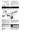
4. Insert two screws into the screw holes.
5. Secure shoulder strap clamp by tighten-
ing screws with a hex wrench.
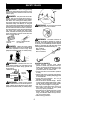
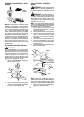
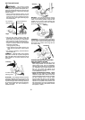
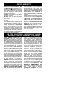
30 inches
(76 cm)
HARNESS
ADJUSTMENT
FOR BALANCE
4 -- 12 inches
(10 -- 30 cm)
above
ground
6 inches
(15 cm)
below
waist
30 inches
(76 cm)
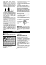
CONFIGURING YOUR UNIT
Yo u can configure your unit using a cutting head
for grass and light weeds, or a weed blade for
cutting grass, weeds, and brush up to 1/2 inch
(1 cm) in diameter . To assemble your unit, go to
the section for the desired configuration and fol-
low the instructions.
ASSEMBLY INFORMATION --
TRIMMER HEAD
TRIMMER
HEAD
NOTE:Remove the b lade andmetal shield b e-
fore attaching the plastic shield and trimmer
head . To re move blade, align hole in the dust
cup with the holein theside ofthe gearbox by
rotating the blade. Insert a small screwdriver
into alignedholes. Th is wil lkeeptheshaftfrom
turning while loosening the blade nut. Remove
blade nut by turning clockwise. Remove the
screwdriver . Remove both washers and blade.
To remove metal shield, loosen and remove the
four mounting screws. See A TTACHING THE
METAL SHIELD a nd INST ALLATION OF THE
METALBLADE f orillustrations. Be sure t ostore
all parts and instructions for future use.
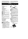
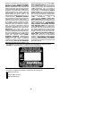
ATTACHING THE PLASTIC SHIELD
AND TRIMMER HEAD
WARNING: The shieldmust beprop-
erly installed. The shield provides partial
protection to theoperator andothers from the
risk of thrown objects, and is equipped with a
line limiterblade whichcuts excess line tothe
proper length. The line limiter blade (on un-
derside of shield) is sharp and can cut you.
1. Remove wing nut from shield.
2. Insert bracket into slot on shield.
3. Pivot shielduntilbolt passes throughhole
in bracket.
4. Tighten the wing nut securely.
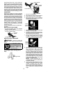
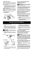
NOTE: If your unit has a plastic cover over
the t hreads onthethreadedshaft, removethe
covering toexpose t hethreads. Beforeinstal-
ling thetrimmer head,make surethe dust cup
and retaining washer are positioned on the
gearbox as shown below.
Wing Nut
Retaining Washer
Dust Cup
Bracket
Slot
Shield
Gearbox
NOTE: Make sure all parts are properly
installed as shown in the illustration before
installing the trimmer head.
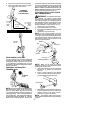
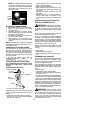
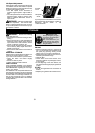
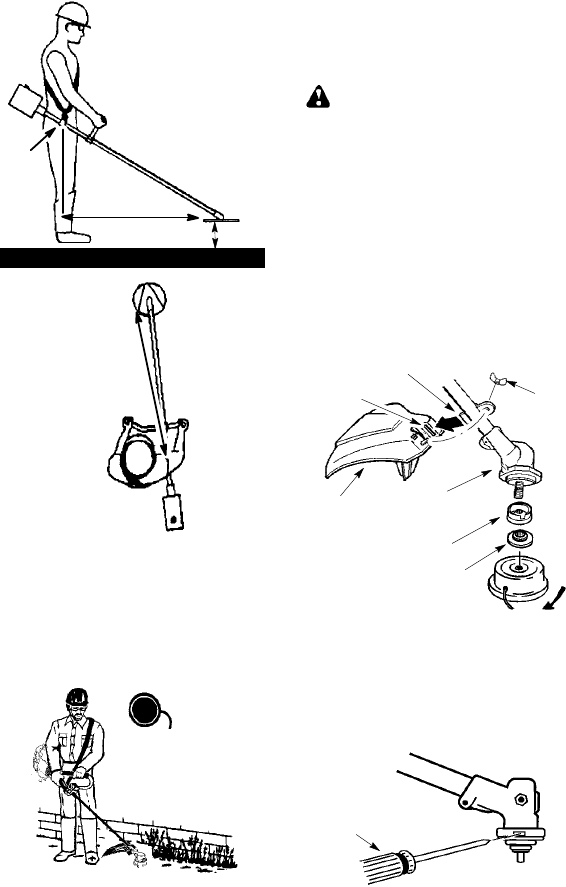
5. Align hole in the dust cup with the hole in
the side of the gearbox by rotating the
dust cup.
6. Insert a small screwdriver into aligned
holes. This will keep the shaft from turn-
ing while tightening trimmer head.
Screwdriver
7. While holdingthe screwdriver in position,
thread trimmer h e ad onto the shaft in the
direction shown on the decal (counter-
clockwise). Tighten until secure.
NOTE: The retaining washer must be posi-
tioned with t he raised section facing toward the
gearbox.