


4
ASSEM BLY
WARNING: If received assembled,
reviewall assembly steps to ensure your unit
is proper ly asse m bled and all fasteners are
secure.
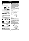
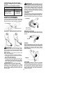
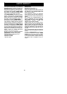
TUBE ASSEMBLY
Wires
Upper Locking Sleeve Assembly
Lower Locking Sleeve Assembly
1. Align upper tube groove with triangle on
lower locking sleeve assembly. Push
tubes together until they snap into place.
Alignment Triangle
Upper Tube
Groove
2. T ry to pull tubes back apart. If the tubes do
not come apart, they are properl y snapped
into place. If the tubes come apart, repe at
step 1 and push unt il the tubes snap into
place.
3. Slide upperlockingsleeveassemblyove r
lower locking sleeve assembly and tight-
en by turning clockwise.
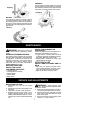
4. Ensu re locking sleeve assem bly and
alignmentdecals appearas illustratedbe-
low.
Alignment decals
WARNING: Failure to co mpletely en-
close e xcess wires in upp er tube duringassem-
bly of the unit m ay resu lt in damage t o the wires
and/or the unit or serious inju ry to the operator
includ ing electro cution .
WARNING: The upper and lower
tubes must be snappedtogether, remain per -
manently assembled togetherand thelocking
sleeve assembly must be fully tightened be-
fore and during use to avoid serious injury to
the operator and/or damage to the unit. DO
NOT attempt to disassemble unit after initial
asse mbly.
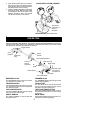
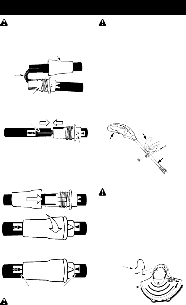
INSTALLATION OF ASSIST HANDLE
1. Loosen and remove wing nut and bolt
from assist handle.
2. Place unit on a flat surface.
3. Firmly push the assist handle over the
tube. To make installation easier, tilt han-
dle toward trigger housing while pushing
down (see illustration).
4. Reinstall bolt in handle. Thread wing nut
onto bolt.
5. Adjustthe handleup ordown the tubeto a
comfortable position; tighten wing nut se-
curely.
Assist handle
Trigger
housing
Tube
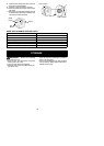
ATTACHING EDGE GUIDE AND
SHIELD
WARNING: The shieldmust b eprop-
erly installed. The shield provides partial
protection from the risk of thrown o bjects to
the operator and others. Your unitis equipped
with a line limiter blade, which cuts excess
line to the proper length while running. The
line limiter blade (on underside of shield) is
sharp and can cut you.
NOTE: If sh ield is not properly instal led, dam-
age to unit (including motor failure ) will result.
1. Insert edge guide into two holes in sh ield.
NOTE: Edge guide mustbe positio ned o n
shield prior to inst allation on motor housing
(see followi ng illustra tion).
Edge Guide
Shield
2. Align the installation arrow on the shield
with the installation arrow on the motor
housing (see illustrat ion below).