


5
ASSEMBLY
WARNING: Stop the unit and dis-
connect f rom the power source before
opening the inlet cover or attempt ing to i n-
sert or remove the in let rest rictor, blower
tube, or vacuum tubes. The motor must
be stopped and the impell er blades no
long er turn ing to av oid serious injury from
the rot at i ng blades.
WARNING: I f recei v ed assembled,
ensur e your uni t is properly assembled
and all fast eners ar e secure.
S A standard screwdriver is required for as-
sembly.
BLOWER ASSEMBLY
NOTE: Assembly inst ructions for using
your uni t as a v acuum foll ow t hi s sect i on.
Attaching the blower tube
Ifyo u have already assembled your unit
for use as a vacuum, referto the section
HOW TO CONVERT UNIT FROM VACUUM
USE TO BLOWER USE.
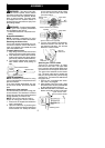
To attach blower tube:
1. Align the grooves on the blower tube
with the gro oveson the blower outlet.
2. Push theb lowertube ontotheblower
outlet untilit snaps into place (tube is
secured by red tube release button).
3. To r emove the blower tube, pr ess the
tube relea se bu tton while pullin g on
tube.
Blower Tube
Blower outlet
Tube Release Button
VACUUM ASSEMBLY
NOTE: Assembly instr uctions for using
yourunitas ablowerareexplained inthe
previous section.
If you have alr ea dy assembled your uni t
for use as a blower, r em ove t he blower
tube.
Remove the inlet restrictor
An inlet r estric tor is used when us ing your
unit as a blower. Thi s restr ict or i s not used
during vacuum use and must be removed
during assembly for vac uum use.
NOTE: Be sure to keep the inlet re-
strictor for using your unit as a blower.
1. Ensur e unit is stopped and ex tension
cord is unplugged.
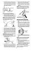
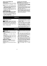
2. Open the inlet cover by inserting the
tip ofa screwdriverinto the latch area
on the blower unit. Gently tilt hand le
of screwdriver toward the front of the
unit to release the latch while pulling
up on the vacu um inlet cover with
your other hand.
Vacuum Inlet Cover (closed)
Latch Area
Bottom view
of unit
Vacuum Inlet Cover (opened)
Latch Area
Impeller
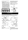
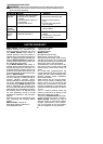
3. Turn the inlet restric tor counterclock-
wise and remove it f rom the unit. Do
not close the inlet door. You will nex t
att ach the vacuum tubes.
Inlet
Restrictor
Vacuum
Inlet Cover
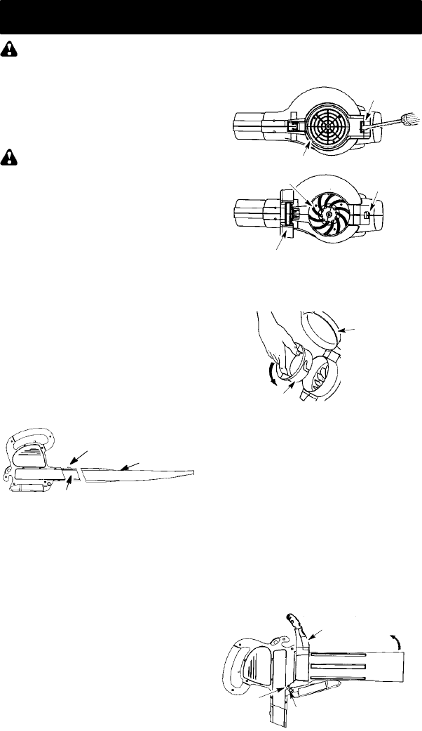
Attaching the vacuum tubes
There are 2 vacuum tubes, an upper
tube and a lower tube. The upper tube
has a vacuum assist handle attached to
one endand is cut straighton bothends.
The upper tube attaches to the blower
unit. The lower tube ha s an angled end
that you point toward the ground during
vacuum use. Thelowertube attaches to
the upper tube.
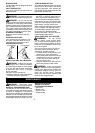
1. Ensure unit is stopped an d exten-
sion c ord is unplugged.
2. W hi l e holding inlet cover open, place
th e h ooks o f the vacuu m assi sthandle
on t he retain ing posts of the u nit .
3. R aise the tube until it is secured to the
blower unit by the red inlet cover latch.
Retaining Post
Vacuum As sist Handle
Upper
V
acuum Tube
Hook