


5
ASSEMBLY
WARNING: Stop the unit and di s-
connect fr om the power source before
opening the inlet c over orattempt ing to in-
sert or remove the inlet restrictor , blower
tube, or vacuum tubes. The motor must
be stopped and the impeller blades no
long er t urnin g to avoid ser ious injury fr om
the r otat i ng bl ades.
WARNING: If r eceived assem bled,
ensur e your uni t is properly assembl ed
and all f astener s ar e secure.
S A standard screwdriver is requir ed for as-
sembly.
BLOWER ASSEMBLY
NOTE: Assemb l y instructi on s for usi ng
your uni t as a vacuum fol l ow t hi s s ecti on.
Attaching the blower tube
Ifyou have already assembled yourunit
for use as avacuum, refer to the section
HOW TO CONVERT UNIT FROM VACUUM
USE TO BLOWER USE.
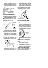
To attach blower tube:
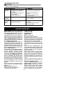
1. Align the grooves on the blowertube
with thegrooves onthe bloweroutlet.
2. Push the blowertubeontotheblower
outlet untilitsnaps intoplace (tube is
secured by red tube release button).
3. To remove the blower t ube, pr ess t he
tube release button while pulling on
tube.
Blower Tube
Blower outlet
Tube Release Bu tton
VACUUM ASSEMBLY
NOTE: Assembly instructions for using
yourunitasablowerareexplainedinthe
previous section.
If you have alr eady assem bled your unit
for use as a blower, remove the bl ow er
tube.
Remove the inlet restrictor
An inlet restrictor is used when using your
unit a s a b l ower. This restri ctoris notused
during v acuum use andmust beremoved
during assembly f or vacuum use.
NOTE: Be sure to keep the inlet re-
strictor for using y our unit a s a blower.
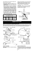
1. Ensure uni t is st opped and extension
cord is unplugged.
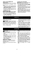
2. Open the inlet cover by inserting the
tip ofasc rewdriverintothe latcharea
on the blower unit. Gently tilt handle
of screwdriver toward the front of the
unit to release the latch while pulling
up on the vacu um inlet cover with
your other hand.
Vacuum Inlet Cover (closed)
Latch Area
Bottom view
of unit
Vacuum Inlet Cover (opened)
Latch Area
Impeller
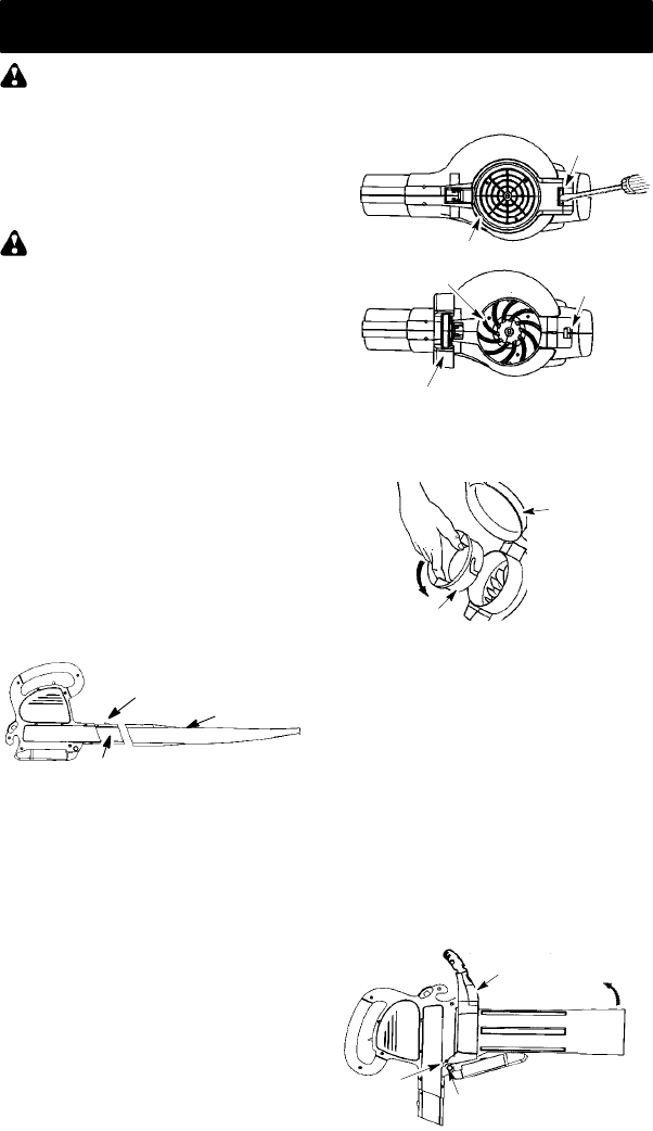
3. T urn the inlet restrictor counterclock-
wise and remove it from the unit. Do
not close the i nl et door. You will next
att ach the vacuum tubes.
Inlet
Restrictor
Vacuum
Inlet Cover
Attaching the vacuum tubes
There are 2 vacuum tubes, an upper
tube and a lower tube. The upper tube
has a vacuum assist handle attached to
oneend andisc ut straighton both ends.
The upper tube attaches to the blower
unit. The lower tube has an angled end
that you point toward the ground during
vacuumuse. Thelowertubeattachesto
the upper tube.
1. Ensure unit is stopped and exten-
sion cord is unplugged.
2. W hil e holdi ng inlet cover open, place
th ehooks o fthe vacuum a ssisthandle
on t h e retaining posts of the unit.
3. Rai se the tube until it is secured to the
blower u ni t by the red i nlet cover latch.
Retaining Post
Vacuum Assist Handle
Upper
V
acuum Tube
Hook