


6
ASSEMBLY INFORMATION -- WEED
BLADE
WEED
BLADE
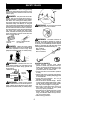
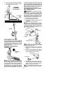
NOTE: Remove the trimmer head and plastic
shield before attaching the metal shield and
installing the weed blade. To remove the trim-
mer head,align h ole i n t he du st cupwith the hole
in the side of the gearbox by rotating the dust
cup. I nsert a small screwdriver into aligned
holes. This will keep the shaft from turning while
loosening the trimmer head. Remove the t rim-
mer head by turning clockwise. R emove the
screwdriver. To r emo ve the plastic shie ld , loos-
en and remove wing nut. Pivot shield to release
bracket from slot. See INSTALLATION OF
THECUTTINGHEADandATTACHINGTHE
PLASTIC S HIELD forillustrations. Be sureto
store all parts and instructions for f uture use.
Never use the trimmer head with the metal
blade installed.
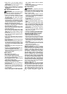
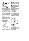
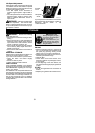
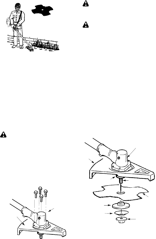
ATTACHING THE METAL SHIELD
WARNING: The metal shield must
be properly installed on the tool anytime the
tool isusedwitha blade.Theforwardtipof the
metal shield helps to reduce the occurrence
of bladethrust which cancause serious injury
such as amputation to the operator or by-
standers. Failure to install the shield in the
position shown can result in serious injury to
the operator. The lengthof the shield must be
aligned with the length o f the shaft.
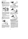
1. Place the metal shield under the gearbox,
and a lign t he screw holes.
Shield
Gearbox
2. Insert and thread the 4 mounting screws
through the holes of the gearbox and the
metal shield. Tightenevenly andsecure-
ly with t he hex wrench provided.
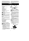
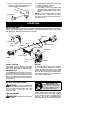
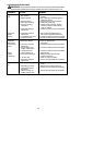
INSTALLATION OF THE METAL
BLADE
WARNING: W ear protective gloves
when handling or performing maintenance on
the blade to avoid injury . The blade is sharp and
can cut you even when it is not moving.
WARNING: Do not use any blades, or
fastening hardware o ther than the washers and
nuts shown in the following illustrations. These
parts must be provided by Poulan/Weed Eater
and installed as shown below . Failure to use
proper parts can cause the blade to fly off and
seriously hurt you or others.
NOTE: The dust cup and retaining washer are
located on t he gearbox shaft andnot in theparts
bag. All other fasteners mentioned in t he follow-
ing assembly steps are in the parts bag.
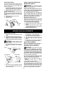
1. Remove the retaining washer from the
threaded shaft of the gearbox. Leave the
dust cup on the shaft.
2. Install the bladeand the r etainingwasher
over the threaded shaft.
3. M ake sure the raised part o f t heretaining
washer is facing the gearbox and the
raised area fits into the hole in the center
of the blade.
4. S lide the blade and retaining washer onto
the shaft of the gearbox.
5. Place the cupped washer ont o the shaft.
Make sure thecupped side ofthe washer
is toward the blade.
6. Install the bladenut bythreading ontothe
shaft counterclockwise.
Shield
Blade
Retaining
Washer
Dust Cup
Cupped
Washer
Nut
Threaded Shaft
Gearbox
NOTE: Make sure all parts are in place as il-
lustrated, and the blade is sandwiched between
the dust cup and the retaining washer. There
should be no space between the blade and the
dust cup or the retaining washer.
7. Align hole in dust cup with hole in side of
gearbox by rotating the blade.