


4
equippedwith asparkarrestingscreen. If y ou
operateina localewheresuch regulationsex-
ist, you are legallyresponsible formaintaining
the oper atingconditionof theseparts. Failure
to do so is a violation of the law. For normal
homeowner use,the mufflerandspark a rrest-
ing screen will not req uire any service. After
50 hours of use, we recommend that your
mufflerbeservicedorreplacedby your autho-
rized service dealer.
ASSEMBLY
CARTON CONTENTS
Check carton contents against the following
list:
S Brushcutter
S Cupped washer
S Large nut for installing blades
S Hex wrench
S Handlebar
S Bracket cover
S Bracket cover screws (2)
S Metal blade shield
S Blade shield screws (4)
S 4--point weed blade
S Plastic shield
S Wing nut (screwed onto plastic shield)
S Shoulder strap with warning
S Container of oil
WARNING: Always stopunit anddis-
connect spark plugbefore performingany as-
sembly procedures.
WARNING: If received assembled,
repeat allsteps to ensure yourunit is properly
assembled and all fasteners are secure.
Examine parts for damage. Do not use dam-
aged parts.
NOTE: If you need assistance or find parts
missing or damaged, call 1-800-554-6723.
It is normal for the fuel filter to rattle in the
empty fuel tank.
Finding fuel or oilresidue on muf fler isnormal
due to carburetor adjustments and testing
done by the manufacturer .
TOOLS REQUIRED
S Hex wrench (provided)
S Adjustable wrench
S Phillips screwdriver
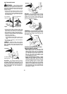
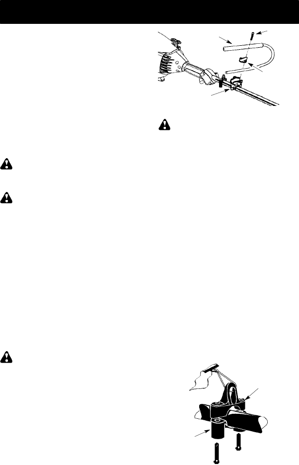
ATTACHING THE HANDLEBAR
DANGER: To avoid serious injury, the
barrier portion of th e handlebar must beinstalled
as shown to provide a barrier between operator
and the spinning blade.
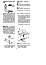
1. Locate the decal on the handlebar. This
decal includes an arrow. Position the
handlebar with the mounting bracket at
the end of t he arrow.
2. Position the bracket cover over the han-
dlebar. Again make sure the handlebaris
at the end of the arrow.
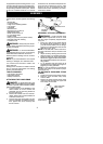
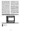
3. Insert screws and hand tighten only. Be
sure the handlebar is installed correctly;
then, tighten each screw securely with
the hex wrench.
Screw
Mounting
Bracket
Handlebar
Bracket Cover
ASSEMBLY OF SHOULDER STRAP
WARNING: Proper shoulder strap
and handlebar ad justments must be made
with the engine completely stopped before
using unit.
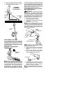
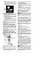
1. Insert your right arm and head through
the shoulder strap and allow it to rest on
your lef t shoulder . Make sure the danger
sign ison your back andthehook istothe
right side of your waist.
NOTE: A one-half twist is built in the shoul-
der strap to allow the strap to rest flat on the
shoulder.
2. Adjust t he strap, allowing the hook to be
about 6 inches (15 cm) below the waist.
3. Fasten the stra p hook to the clam p located
between the trigger handle a nd the handle-
bar clamp base and lift the tool to the oper-
ating position.
4. Try on shoulder strap and adjust for fit
and balance before starting the engineor
beginning a cutting operation.
NOTE: It may be necessary to relocate the
shoulder strap clamp on the shaft for proper
balancing of unit.
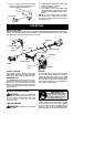
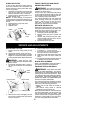
TO RELOCATE SHOULDER STRAP
CLAMP:
1. Loo sen and remove both clamp screws.
2. Place the upper shoulder strap clamp
over the shaft.
3. Position the lower shoulder strap clamp
under the shaft and align the upper and
lower clamp screw holes.
Upper Shoulder
Strap Clamp
Screws
Lower Shoulder
Strap Clamp