


10
If the unit still doesn’t start, refer to
TROUBLESHOOTING TABLE or call
1-800-554-6723.
OPERATING THE COUPLER
This m odel is equipped with a c oupler which
enables optional attachments to be installed.
The optional attachments a re:
MODEL:
Edger
1000E.......................
Cultivator
2000T...................
Blower
3000B......................
Brushcutter
4000C.................
WARNING:
Always stop unit and dis-
connect spark p lug before removing or instal-
ling attachments.
REMOVING TRIMMER ATTACH-
MENT (OR OTHER OPTIONAL AT-
TACHMENTS)
CAUTION:
When removing or ins t alling at-
tachments, place the unit on a flat surface for
stability.
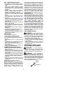
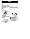
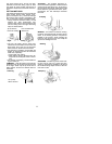
1. Loosen the coupler by turning the knob
counterclockwise.
Coupler
Knob
LOOSEN
TIGHTEN
Upper Tube
Lower
Attachment
2. Press and hold t he locking/release button.
Locking/Release
Button
Coupler
Upper Tube
Lower Attachment
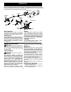
3. While securely holding the engine and
upper tube, pull the at tachment straight
out of the coupler.
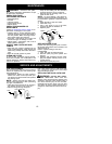
INSTALLING OPTIONAL ATTACH-
MENTS
1. Remove the tube cap from the attach-
ment (i f present).
2. Position locking/release button of attach-
ment into guide recess of coupler.
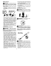
3. Push the attachment into the coupler until
the locking/release button s naps into the
primary hole.
4. Before using the unit, tighten the knob se-
curely by turning clockwise.
Coupler
Primary Hole
Upper
Tube
Locking/
Release
Button
Attachment
Guide Recess
WARNING:
Make sure the locking/
release button is locked i n the primary hole
and the knob is securely tightened before op-
erating the unit.
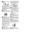
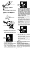
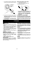
OPERATING POSITION
Eye Protection
Long P ants
Heavy Shoes
ALWAYS WEAR:
Cut from your right t o your left.
WARNING:
Always weareyeprotec-
tion. Never lean over the trimmer head.
Rocks ordebris canricochet orbe throwninto
eyes and face and cause blindness or other
serious injury.
Do not run the engine at a higher speed than
necessary. The cutting line will cut efficiently
whenthe engine isrunat less t han fullthrottle.
At lower speeds, there is less engine noise
and vibration. The cutting line will l ast longer
and will be less likely to “weld” ont o the spool.
Always release the throttle trigger and allow
the engine to return to idle speed when not
cutting.
To stop engine:
S
Release the throttle trigger.
S
Move the ON/OFF switch to the OFF posi-
tion.
TRIMMER LINE ADVANCE
The cutting head advances line automati-
cally. Do nottap head on the ground toad-
vance line.
This may break parts and cause
cutting head to m alfunction.
Upon unit start up, the line will advance auto-
matically t o the correct cutting pat h length.
Always keep the shield in place when the tool
is being operated.
WARNING:
Use only .080” (2 mm)
diameter round line.
Other sizes and
shapes of line will not advance properly and
will result in improper cutting head function or