


9
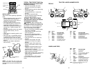
CHECKLIST
BEFORE YOU OPERATE AND ENJOY
YOUR NEW TRACTOR, WE WISH TO
ASSURE THAT YOU RECEIVE THE
BEST PERFORMANCE AND
SATISFACTION FROM THIS QUALITY
PRODUCT.
PLEASE REVIEW THE FOLLOWING
CHECKLIST:
✓ All assembly instructions have been
completed.
✓ No remaining loose parts in carton.
✓ Battery is properly prepared and
charged. (Minimum 1 hour at 6
amps).
✓ Seat is adjusted comfortably and
tightened securely.
✓ All tires are properly inflated. (For
shipping purposes, the tires were
overinflated at the factory).
✓ Be sure mower deck is properly
leveled side-to-side/front-to-rear for
best cutting results. (Tires must be
properly inflated for leveling).
✓ Check mower and drive belts. Be sure
they are routed properly around pulleys
and inside all belt keepers.
✓ Check wiring. See that all connections
are still secure and wires are properly
clamped.
WHILE LEARNING HOW TO USE YOUR
TRACTOR, PAY EXTRA ATTENTION TO
THE FOLLOWING IMPORTANT ITEMS:
✓ Engine oil is at proper level.
✓ Fuel tank is filled with fresh, clean,
regular unleaded gasoline.
✓ Become familiar with all controls - their
location and function. Operate them
before you start the engine.
✓ Be sure brake system is in safe
operating condition.
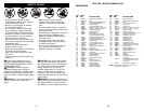
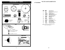
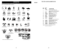
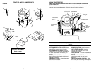
CHECK TIRE PRESSURE
The tires on your tractor were overin-
flated at the factory for shipping pur-
poses. Correct tire pressure is important
for best cutting performance.
• Reduce tire pressure to PSI shown in
“PRODUCT SPECIFICATIONS”
section of this manual.
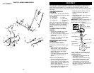
CHECK FOR PROPER POSITION
OF ALL BELTS
See the figures that are shown for
replacing motion and mower blade drive
belts in the Service and Adjustments
section of this manual. Verify that the
belts are routed correctly.
CHECK DECK LEVELNESS
For best cutting results, mower housing
should be properly leveled. See “TO
LEVEL MOWER HOUSING” in the
Service and Adjustments section of this
manual.
CHECK BRAKE SYSTEM
After you learn how to operate your
tractor, check to see that the brake is
properly adjusted. See “TO ADJUST
BRAKE” in the Service and Adjustments
section of this manual.
40
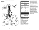
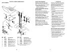
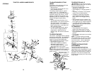
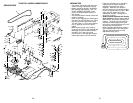
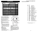
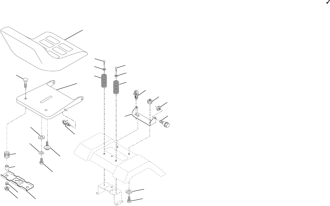
TRACTOR -- MODEL NUMBER 259723
SEAT ASSEMBLY
26
23
1
24
16
15
12
13
17
25
4
3
8
9
7
8
9
7
2
6
22
21
5
10
5
14
1 127426X Seat
2 140551 Bracket Pvt St
3 71110616 Bolt Fin Hex 3/8-16unc X 1
4 19131610 Washer Flat 13/32 X 1X10 Ga
5 145006 Clip Push-In Hinged
6 73800600 Nut Crownlock 3/8-16 UNC
7 124181X Spring Seat Cprsn 2 250 Blk
8 17000616 Screw 3/8-16 X 1-1/2
9 19131614 Washer 13/32 X 1 X 14 Ga
10 155925 Pan Seat
12 121246X Bracket Mounting Switch
13 121248X Bushing Snap Blk Nyl 50 Id
14 72050412 Bolt Rdhd Sht 1/4-20x1-1/2
15 134300 Spacer Split 28x 96 Yel Zinc
16 121250X Spring Cprsn 1 27 Blk Pnt
17 123976X Nut Lock 1/4 Lge Flg Gr 5
21 171852 Bolt Shld 5/16-18 Unc-2A
22 73800500 Nut Crown Lock Hex 5/16-18
23 74780814 Bolt Fin Hex 1/2-13 x 7/8 Gr5
24 19171912 Washer 17/32 X1-3/16X12 Ga
25 127018 Bolt Shoulder
26 10040800 Washer Lock Hvy Hlcl 1/2
KEY PART
NO. NO. DESCRIPTION
NOTE: All component dimensions given in U. S.
inches 1 inch = 25/4 mm
KEY PART
NO. NO. DESCRIPTION