


8
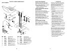
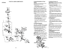
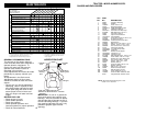
Flat Washer
Seat
Seat Pan
Shoulder
Bolt
Adjustment
Bolt
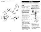
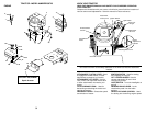
TO DRIVE TRACTOR OFF SKID
(See Operation section for location
and function of controls)
WARNING: Before starting, read,
understand and follow all instructions in
the Operation section of this manual. Be
sure tractor is in a well-ventilated area.
Be sure the area in front of tractor is
clear of other people and objects.
• Be sure all the above assembly steps
have been completed.
• Check engine oil level and fill fuel
tank with gasoline.
• Sit on seat in operating position,
depress clutch/brake pedal and set
the parking brake.
• Place gear shift lever in neutral (N)
position.
• Press lift lever plunger and raise
attachment lift lever to its highest
position.
• Start the engine. After engine has
started, move throttle control to idle
position.
• Depress clutch/brake pedal into full
“BRAKE” position and hold. Move
gearshift lever to 1st gear.
• Slowly release clutch/brake pedal and
slowly drive tractor off skid.
• Apply brake to stop tractor, set parking
brake and place gearshift lever in
neutral position.
• Turn ignition key to “OFF” position.
Continue with the instructions that
follow.
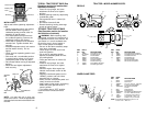
TO ROLL TRACTOR OFF SKID (See
Operation section for location and
function of controls)
• Press lift lever plunger and raise
attachment lift lever to its highest
position.
• Release parking brake by depressing
clutch/brake pedal.
• Place gearshift lever in neutral (N)
position.
• Roll tractor forward off skid.
• Remove banding holding discharge
guard up against tractor.
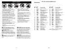
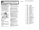
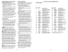
Battery Box
Door
Seat Pan
Label
Terminal
Terminal
NOTE: You may now roll or drive your
tractor off the skid. Follow the appropriate
instruction below to remove the tractor from
the skid.
INSTALL SEAT
Adjust seat before tightening adjustment
knob.
• Remove adjustment bolt, lock washer
and flat washer securing seat to
cardboard packing and set aside for
assembly of seat to tractor.
• Pivot seat upward and remove from
the cardboard packing. Remove the
cardboard packing and discard.
• Place seat on seat pan and assemble
shoulder bolt. Tighten shoulder bolt
securely.
• Assemble adjustment bolt, lock washer
and flat washer loosely. Do not
tighten.
• Lower seat into operating position and
sit on seat.
• Slide seat until a comfortable position
is reached which allows you to press
clutch/brake pedal all the way down.
• Get off seat without moving its adjusted
position.
• Raise seat and tighten adjustment
knob securely.
Lock Washer
41
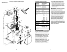
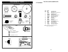
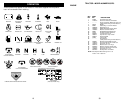
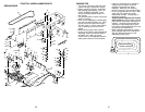
TRACTOR -- MODEL NUMBER 259723
DECALS
15
4
8
3
5
13
KEY PART
NO. NO. DESCRIPTION
1 156867 Decal Oper P/L Eng
2 64-1726-29 Decal Engine HP
3 164578 Decal Hood Rh
4 164579 Decal Hood Lh
5 162398 Decal Ins Strg Whl
8 164424 Decal Panel Dash
9 171448 Decal Fender Logo
10 145005 Decal Battery Dngr/Psn
11 156439 Decal Danger Fender
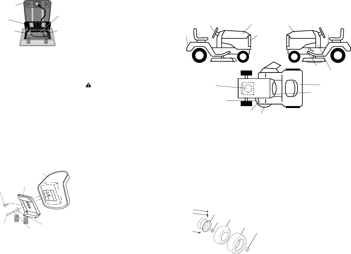
WHEELS AND TIRES
1 59192 Cap Value Tire
2 65139 Stem Value
3 106222X Tire F Ts 15 X 6 0 - 6 Service
4 59904 Tube Inner Front #35060
5 106732X427 Rim Asm 6"front White
Service
6 278H Fitting Grease
7 9040H Bearing Flange
8 106108X427 Rim Asm 8"rear White Service
9 124635X Tire R Ts 18x8 5-8 Service
10 7152J Tube Rear 9 5 X 8 Service
11 104757X Cap Axle Blk 1 50 X 1 00
- - 144334 Sealant, Tire (10 oz. tube)
6
2
1
5,8
4,10
3,9
11
7
9
11
2
1
12
KEY PART
NO. NO. DESCRIPTION
12 4900J Decal Clutch/brake English
15 136832 Decal Mower Drive Schem 38
18 163128 Decal Mower Enviro
21 162392 Decal Grille Logo
- - 138311 Decal Lift Handle
- - 173487 Manual Owners English
- - 173488 Manual Owners Spanish
KEY PART
NO. NO. DESCRIPTION
NOTE: All component dimensions given in U. S.
inches 1 inch = 25/4 mm
18
21
10